|
Gx series of CCD cameras are equipped with USB 2.0 interface with
480 Mbps transfer speed. USB interface brings numerous advantages
beside the very high transfer speed. For instance USB connectors and
cables contain also lines dedicated to provide power to attached
devices, so the G0 and G1 cameras are connected to the host computer
only by single cable (power requirement of the cooled CCD cameras of
G2, G3 and G4 series is significantly greater than the USB line can
provide and these cameras use their own power supply). USB cables are
standardized, which is why they cannot be confused and plugged the
wrong way etc. Also software support of USB devices is designed from
the ground up to provide “Plug-and-Play” experience. Users need
not to perform any device configuration, assign unique addresses
etc.
A disadvantage of USB connection is the limited distance between a
host PC and USB device. The maximum length of single USB cable is
limited to 5 meters. This distance can be prolonged to 10 or 15 meters
with the help of so-called Active USB Extenders, but a cable
connection and active USB repeater (hub) must be placed every 5
meters. Very long USB connections can be also power-limited. The
energy, provided by the host PC, is consumed by active repeaters and
also long power lines with non-zero electrical resistance cause drop
of supply voltage.
The problem of connection of Gx CCD cameras over a long distance is
solved by Gx Camera Ethernet Adapter, offering remote camera
connection over Ethernet interface. The core of the adapter is an
embedded computer with a software is placed on the local Flash
storage.
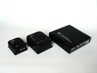
Gx Camera Ethernet Adapter in the micro (left), mini
(center) and standard (right) variants Three models of the Gx Camera Ethernet Adapters are
available:
The largest “standard” variant uses a PC-compatible
motherboard equipped with the Intel Atom processor. No moving parts
are present in the device, the processor needs no fan and is cooled
only passively. This variant is powered by single 12 V DC line, the
same like the G2, G3 an G4 cameras. Also power line connectors are
the same, so the device can be powered like the rest of the
setup. Medium variant of the Gx Camera Ethernet Adapter called
“mini” is also based on the PC-compatible motherboard, but a
smaller one called NUC (an abbreviation from Next Unit of
Computing). These motherboards can have higher computational power
and thus also higher TDP, so they can be equipped with a small
cooling fan. Mini-variant of the adapter if powered from 19 V DC
adapter (similarly to many laptop and notebook computers), supplied
with the device. The smallest “micro” variant of the Gx Camera Ethernet
Adapter is based on the ARM architecture. It is powered from a
single 12 V DC line, like the standard variant (and like all G2, G3
and G4 cameras).
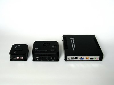
Ethernet and USB interfaces of the Gx Camera Ethernet
Adapter devices Regardless of different processors and in the case of Micro variant
also different processor architecture, all devices employ multiple
cores and at last 1 GB of on-board memory
to be able to comfortably store full frames from even in the case all
four connected cameras are the ones with the largest-resolution
available. This is important to for the network connected device,
because no isochronous data packet transfer and no delivery time can
be guaranteed over a general network. Also all devices use the same
software stack and are completely software compatible from the driver
point of view.
The Gx Camera Ethernet Adapter Micro with G2 camera (left)
and with G3 camera equipped with EFW (right) The used Ethernet interface supports both 1 Gbps and slower
10/100 Mbps transfer speeds and it can be connected to all common
local area networks. If the 1 Gbps interface is used and the download
operations from multiple cameras do not overlap, the difference
between download time of directly USB connected camera and camera
connected over the Gx Camera Ethernet Adapter is negligible.
Despite differences in size and construction, function and
usage of all variants are identical Device configuration
Every device providing services to clients over TCP/IP network
must have a fixed IP address assigned to be continuously
accessible. Configuration of the Gx Camera Ethernet Adapter
network interface (assigning of the IP address, definition of the
network mask and default gateway etc.) is performed using WWW
interface. When the device is powered for the first time,
the following parameters are preset:
| IP Address |
192.168.0.5 |
| Network mask |
255.255.255.0 |
| Gateway |
192.168.0.1 |
| DNS server |
192.168.0.1 |
| Port |
48899 |
To be able to connect to the device for the first time, it is
necessary to attach it to the network with above defined
parameters (it is enough to connect the device directly to the
computer with properly set network parameters with an Ethernet
cable). Then it is possible to connect the device to the desired
network after the configuration is updated.
Configuration is performed through WWW interface and any web
browser can be used to access it. The WWW configuration interface
is not available all the time the device is running, but it is
stopped after two minutes from the time the device is powered up
from the security reasons. This measure prohibits unwanted
configuration changes when the device is accessible from many
different computers.
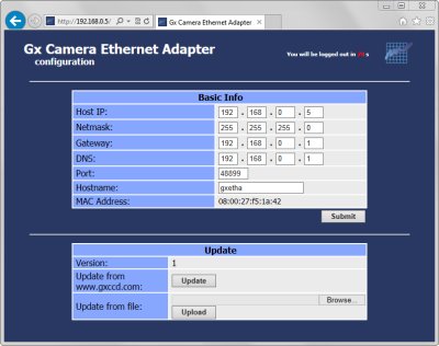
Device configuration through WWW interface Connection over WiFi network
The Ethernet port of the adapter device can be attached to
arbitrary WiFi bridge device to access attached cameras
wirelessly. However, such solution needs another box (the
Ethernet/WiFi bridge device) with another power supply etc. This
is why the Gx Camera Ethernet Adapter firmware was extended with
support for USB/WiFi interfaces.
The WiFi adapter can be plugged into any USB port. The Gx
Camera Ethernet Adapter then can be added to any existing WiFi
network.
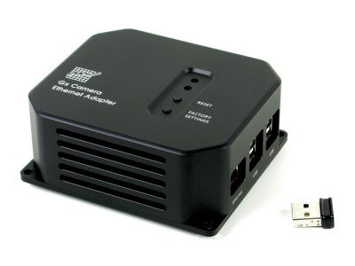
The USB/WiFi adapter is plugged into one USB
port Because the WiFi adapter antenna is located outside of the
device metal case, the signal reception is better compared to
devices employing WiFi adapter with antenna soldered on the
electronics circuits board. The USB 2.0 HiSpeed transfer rate
480 Mbps typically do not bottleneck the WiFi transfers, which are
usually slower.
Device with attached USB/WiFi adapter has to be configured over
a wired Ethernet connection exactly like the standard Gx Camera
Ethernet Adapter. However, the configuration page offers the WiFi
adapter configuration section.
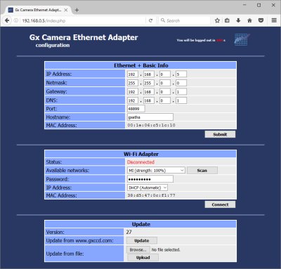
USB/WiFi adapter configured to obtain IP address
dynamically through DHCP There are two possibilities how to assign the WiFi adapter IP
address. The first possibility is to let the DHCP server assign
it. Because the Gx Camera Ethernet Adapter is accessed as a
server, it is necessary to assign a fixed address to it, so the
clients always know the address to which they should connect. It
is usually a task of the DHCP server configuration, which allows
assigning a particular IP address to the device with defined MAC
address.
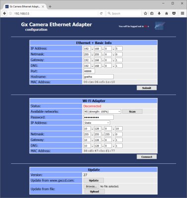
USB/WiFi adapter with manually configured IP
address Another possibility is to configure the IP address of the Gx
Camera Ethernet Adapter manually.
The properly configured USB/WiFi interface can then be connect
to WiFi network. The configuration page indicates successful
connection.
Currently supported USB/WiFi chipsets are:
Realtek RTL8192CU/RTL8188CU/RTL8187
ASUS USB-N10 Nano, USB-N13 D-Link DWA-121, DWA-131, DWA-135 TP-LINK TL-WN82xN Netgear N150, N300 Belkin Surf USB Micro Ralink/MediaTek
RT257x/RT2671/RT2770/RT2870/RT307x/RT3572
ASUS USB-N13, USB-N14, USB-N66, USB-N53 Linksys AE3000 Netgear WNDA4100 ZyXEL N220 D-Link DWA-137, DWA-140, DWA-160, DWA-162 Atheros
AR5007UG/AR2524/AR5523/AR5524/AR7010/AR9271
Netgear WNA1100li TP-LINK TL-WN72xN D-Link DWA-126 Atmel AT76C50x Broadcom BCM43143/BCM43242/4320 Marvell 88W8388/88W8797
Handling of the device
Standard variant
The standard Gx Camera Ethernet Adapter device can be
powered from direct current power supply 8 to 19 V DC. Power
connector is located on the left side of the unit back panel.
The connector is standard 5,5/2,5 mm. Plus pole is on the
inner pin, neutral (ground) pole on the connector outer
jacket.
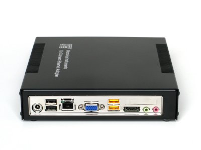
Gx Camera Ethernet Adapter back panel with
connectors Universal 12 V DC AC/DC power supply is shipped with the Gx
Camera Ethernet Adapter. The supply input voltage is
100-240 V AC/50-60 Hz.
| Gx Ethernet Adapter power |
8 to 19 V DC |
| Power consumption |
8.5 W without attached cameras |
| |
17 W with four G1 cameras |
| Power supply input voltage |
100-240 V AC/50-60 Hz |
| Power supply output voltage |
12 V DC/5 A |
Gx Camera Ethernet Adapter is configured to start
immediately after power line is connected. However, it can be
switched off and on when powered with the ON/OFF button on the
device front panel.
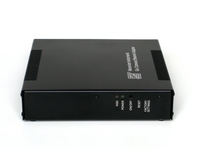
Gx Camera Ethernet Adapter front panel with
buttons Two more buttons RESET and FACTORY SETTINGS are also on the
front panel. RESET reboots the device and FACTORY SETTINGS
restores the default parameters (device configuration is
described thoroughly in the following chapters).
| Dimensions |
188 × 184 × 40 mm |
| Weight |
0.7 kg |
Gx Camera Ethernet Adapter unit mechanical
properties Mini variant
The mini-variant of the Gx Camera Ethernet Adapter device
is powered from 19 V DC power supply. Power connector is
located on the side of the unit. The connector is standard
5,5/2,5 mm. Plus pole is on the inner pin, neutral (ground)
pole on the connector outer jacket.
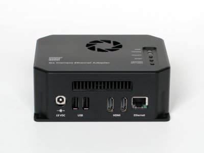
Gx Camera Ethernet Adapter mini-variant side
connectors Universal 19 V DC/65 W power supply is supplied with the Gx
Camera Ethernet Adapter. The supply input voltage is
100-240 V AC/50-60 Hz.
| Gx Ethernet Adapter power |
19 V DC |
| Power consumption |
7 W without attached cameras |
| |
15.5 W with four G1 cameras |
| Power supply input voltage |
100-240 V AC/50-60 Hz |
| Power supply output voltage |
1 V DC/3.4 A |
Gx Camera Ethernet Adapter is configured to start
immediately after power line is connected. However, it can be
switched off and on when powered with the ON/OFF button on the
device top side.
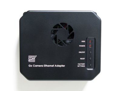
Buttons on the top side of Gx Camera Ethernet
Adapter mini-variant Two more buttons RESET and FACTORY SETTINGS are also on the
front panel. RESET reboots the device and FACTORY SETTINGS
restores the default parameters (device configuration is
described thoroughly in the following chapters).
| Dimensions |
128 × 111 × 50 mm |
| Weight |
0.6 kg |
Gx Camera Ethernet Adapter unit mechanical
properties Micro variant
The micro variant of the Gx Camera Ethernet Adapter device
can be powered from direct current power supply 10 to 30 V DC.
Power connector is located on the side of the unit. The
connector is standard 5,5/2,5 mm. Plus pole is on the inner
pin, neutral (ground) pole on the connector outer jacket.
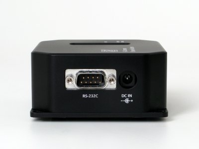
Gx Camera Ethernet Adapter side panel with
connectors Universal 12 V DC AC/DC power supply is shipped with the Gx
Camera Ethernet Adapter. The supply input voltage is
100-240 V AC/50-60 Hz.
| Gx Ethernet Adapter power |
10 to 30 V DC |
| Power consumption |
2 W without attached cameras |
| |
10 W with four G1 cameras |
| Power supply input voltage |
100-240 V AC/50-60 Hz |
| Power supply output voltage |
12 V DC/5 A |
Gx Camera Ethernet Adapter is configured to start
immediately after power line is connected.
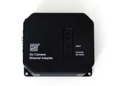
Gx Camera Ethernet Adapter Micro top side with
buttons Two more buttons RESET and FACTORY SETTINGS are also on the
front panel. RESET reboots the device and FACTORY SETTINGS
restores the default parameters (device configuration is
described thoroughly in the following chapters).
| Dimensions |
95 × 83 × 39 mm |
| Weight |
0.3 kg |
Gx Camera Ethernet Adapter unit mechanical
properties Camera connection
Single Gx Camera Ethernet Adapter can attach up to four G0 to
G4 cameras to the control PC using the Ethernet interface. It is
worth noting that the device is not an ordinary USB/Ethernet
converter, just tunneling USB data over the TCP/IP network (such
converters usually do not work properly with all devices and their
usage brings numerous problems and is not reliable). The Gx Camera
Ethernet Adapter handles attached Gx cameras the same way like the
host PC, there is no difference from the camera point of view
in command sequences and especially timing, transfer speeds
etc.
Quite opposite situation is on the control PC. There are
fundamental differences between the camera connected directly to
the USB port and the camera connected through the Gx Camera
Ethernet Adapter. Cameras behave like two totally different and
incompatible devices – the USB interface is used in the first
case, TCP/IP network sockets interface in the second case
(Gx camera and the Gx Ethernet Adapter behaves like a single
device).
No USB device system drivers are to be installed on the control
PC in the second case (and also system drivers for any other
device are not installed), USB interface is not used to
communicate with camera at all. The control computer communicates
with the camera using the TCP/IP protocol only.
This is also why drivers for client programs (SIPS, ASCOM,
MaxIm DL, …) are also different and a driver intended for camera
connected to USB does not work with camera connected over
Ethernet.
Let us note that unlike USB, the Ethernet interface (and TCP/IP
network) is not designed to be “Plug-and-play”. If the
connection to different computer (server) is to be established,
its IP address or domain name must be known. So even before the
control computer can connect to the Gx Camera Ethernet Adapter,
the IP address or domain name of the particular device must be
defined.
For instance every attached USB camera is immediately displayed
in the SIPS (Scientific Image Processing System) software Camera
configuration tool window and the user may choose the camera as
imager or guider. And when no USB camera is connected, SIPS does
not offer such cameras despite the camera driver is present and
active.
On the other hand, cameras with Ethernet interface require the
possibility to configure the IP address or domain name. This is
why when the driver for cameras connected over the Ethernet is
present in the SIPS, the software always displays a line “Gx
Ethernet Adapter”, marked as “unconfigured”. When this
line is selected, it is possible to open a dialog box allowing
definition of IP address or domain name by clicking the
“Configure” button.
Other programs may offer different ways to configure (define
the IP address) the Gx Camera Ethernet Adapter.
Warning: Gx Camera Ethernet Adapter is supported in SIPS version
2.2 and later. For other software packages, a driver designed for Gx
Camera Ethernet Adapter must be used, driver intended for USB
connected cameras does not work. | 