|
G0 and G1 cameras are very compact, lightweight and easy to
operate. The user only needs to insert it into telescope focuser, plug
the USB cable to the computer and it works.
Sensitivity is an important feature of any guider. It must
provide images of guiding star(s) with sufficient S/N ratio in
rather short time to ensure perfect guiding. The necessity to
accumulate light for many tens of seconds or even minutes is often
unacceptable for high quality guider. This is why the G1 cameras
utilize sensitive Sony ICX CCDs.
Sony EXview HAD CCDs have better than 50% quantum efficiency
and low read noise. G0/G1 cameras support 16-bits digitization, significantly
enhancing the dynamic range. Strong anti-blooming protection keeps even bright stars
round, without blooming streaks. G0/G1 cameras also provide very fast readout—pixel digitization speed reaches 8 MPx/s in fast read mode. G0/G1 cameras ensure very low readout noise.
Both G0 and G1 series of CCD cameras contain similar
electronics, same CCD detectors and provide similar functionality.
The difference is mainly in mechanical construction and in
cooling.
G0 cameras offer round body, which is more compact compared
to G1 series, which could be important e.g. in combination with
Off-Axis Guider etc. G1 cameras are slightly bigger and heavier, but they keep the
CCD detector on lower temperature thanks to embedded fan, which more
than two times lowers detector dark current. They also offer
CS-thread adapter and also other alternatives of lens adapters
(Canon EOS and Nikon bayonets, T-thread etc.).
G0 and G1 cameras do not require any external power supply,
they are powered entirely from the host computer through the USB
cable. Because the power provided by USB line is rather limited,
these cameras do not use energy-hungry Peltier cooler. G1 cameras
contain small fan, which helps keeping the CCD temperature on the
environment temperature to significantly reduce dark
current.
G0 and G1 cameras are USB-powered devices (only 1 cable is
necessary to operate). Absence of the Peltier cooler does not allow CCD operation
temperature below ambient temperature, but fan embedded in G1
cameras keeps the CCD temperature very close.
Although modern astronomical telescope mounts support
guiding through PC connection, G0 and G1 cameras incorporate
standard 6-pin connector for the mount autoguider input. Thus the
computer can guide the mount through the camera even in the case
there is no link between the telescope mount and the PC.
The G1 camera head is equipped with standard Autoguider
connector. 
USB and Autoguider ports on G0 and G1 cameras SIPS (Scientific Image Processing System) control software
supports both guiding through the camera port as well as through
PC-to-telescope link.
The Autoguider port on the G0 or G1 camera head follows the
standard pinout introduced by the ST-4 guiding camera:
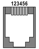 |
| 1 |
R.A. + (Right) |
| 2 |
Dec + (Up) |
| 3 |
Dec – (Down) |
| 4 |
R.A. – (Left) |
| 5 |
Common (Ground) |
| 6 |
Not connected |
|
G0 and G1 series of CCD cameras is intended for guiding as
well as for CCD imaging, they are very capable to capture
astronomical or microscopic images. G1 cameras can be used with any
telescope or C/CS-mount compatible lens.
G0 series of CCD cameras include the following models. The letter C
indicates the CCD with color mask is used, which enables acquiring of
color images in single exposure.
| Model |
CCD chip |
CCD architecture |
Color filters |
Resolution |
Pixel size |
Imaging area |
Download time |
| G0-0300 |
ICX424AL |
progressive |
none |
656 × 494 |
7.4 × 7.4 μm |
4.9 × 3.7 mm |
~ 0.05 s |
| G0-0300C |
ICX424AQ |
progressive |
RGBG (Bayer) |
656 × 494 |
7.4 × 7.4 μm |
4.9 × 3.7 mm |
~ 0.05 s |
| G0-0800 |
ICX204AL |
progressive |
none |
1032 × 778 |
4.65 × 4.65 μm |
4.8 × 3.6 mm |
~ 0.1 s |
| G0-0800C |
ICX204AK |
progressive |
RGBG (Bayer) |
1032 × 778 |
4.65 × 4.65 μm |
4.8 × 3.6 mm |
~ 0.1 s |
| G0-2000 |
ICX274AK |
progressive |
none |
1628 × 1236 |
4.4 × 4.4 μm |
7.2 × 5.4 mm |
~ 0.25 s |
| G0-2000C |
ICX274AQ |
progressive |
RGBG (Bayer) |
1628 × 1236 |
4.4 × 4.4 μm |
7.2 × 5.4 mm |
~ 0.25 s |
G1 series of CCD cameras currently include the following models.
The letter C indicates the CCD with color mask is used, which enables
acquiring of color images in single exposure.
| Model |
CCD chip |
CCD architecture |
Color filters |
Resolution |
Pixel size |
Imaging area |
Download time |
| G1-0300 |
ICX424AL |
progressive |
none |
656 × 494 |
7.4 × 7.4 μm |
4.9 × 3.7 mm |
~ 0.05 s |
| G1-0300C |
ICX424AQ |
progressive |
RGBG (Bayer) |
656 × 494 |
7.4 × 7.4 μm |
4.9 × 3.7 mm |
~ 0.05 s |
| G1-0301 |
ICX414AL |
progressive |
žádné |
656 × 494 |
9.9 × 9.9 μm |
6.5 × 4.9 mm |
~ 0.05 s |
| G1-0301C |
ICX414AQ |
progressive |
RGBG (Bayer) |
656 × 494 |
9.9 × 9.9 μm |
6.5 × 4.9 mm |
~ 0.05 s |
| G1-0800 |
ICX204AL |
progressive |
none |
1032 × 778 |
4.65 × 4.65 μm |
4.8 × 3.6 mm |
~ 0.1 s |
| G1-0800C |
ICX204AK |
progressive |
RGBG (Bayer) |
1032 × 778 |
4.65 × 4.65 μm |
4.8 × 3.6 mm |
~ 0.1 s |
| G1-1200 |
ICX445ALA |
progressive |
none |
1296 × 966 |
3.75 × 3.75 μm |
4.9 × 3.6 mm |
~ 0.15 s |
| G1-1200C |
ICX445AQA |
progressive |
RGBG (Bayer) |
1296 × 966 |
3.75 × 3.75 μm |
4.9 × 3.6 mm |
~ 0.15 s |
| G1-1400 |
ICX285AL |
progressive |
no |
1392 × 1040 |
6.45 × 6.45 μm |
9.0 × 6.7 mm |
~ 0.18 s |
| G1-1400C |
ICX285AQ |
progressive |
RGBG (Bayer) |
1392 × 1040 |
6.45 × 6.45 μm |
9.0 × 6.7 mm |
~ 0.18 s |
| G1-2000 |
ICX274AK |
progressive |
none |
1628 × 1236 |
4.4 × 4.4 μm |
7.2 × 5.4 mm |
~ 0.25 s |
| G1-2000C |
ICX274AQ |
progressive |
RGBG (Bayer) |
1628 × 1236 |
4.4 × 4.4 μm |
7.2 × 5.4 mm |
~ 0.25 s |
While the monochrome CCD captures all incoming wavelengths (to
which the detector is sensitive) by all pixels, color CCD detector has
red, green and blue filters applied on individual pixels, arranged to
so-called Bayer mask. Monochrome CCD is substantially more sensitive,
but it is necessary to perform multiple exposures through color
filters if we want to capture color image. Color detector on the other
side limits the incoming light by color filters, but enables
reconstruction of color image from single exposure, even if the color
resolution is lower than is the CCD pixel matrix.
Monochrome (left) and color (right) CCD Although the so-called Full Frame (FF) CCDs reach maximal
sensitivity, they can be used only in conjunction with mechanical
shutter. The so-called Interline Transfer (IT) CCDs are equipped with
electronic shutter, allowing very short exposures, on the other side.
This is why the G1 cameras use IT detectors. Also IT sensors differ by
means of image read—while the progressive read
chips can read all image pixels at once, interlaced read CCDs divide
the frame to two half-frames containing only odd or only even rows and
read the independently.
Progressive read CCD (left) and interlaced read CCD
(right) More information about CCD chip architecture can be found in the
Introduction to the CCD Imaging article on our web
site.
G0 and G1 guider cameras are designed to work in
cooperation with a host Personal Computer (PC). The guiding
algorithms are performed by a PC, not by the camera itself. To
operate the camera, you need a computer which:
Is compatible with a PC standard. Runs a modern 32-bit or 64-bit Windows operating
system. Provides at last one free USB port.
G1 Cameras Technical Specifications
CCD Chip
G0 and G1 cameras use sensitive and low noise Sony ICX CCD
detectors. Sony does not publish the absolute quantum
efficiency of these CCDs, but the estimated QE exceeds
50 %. The dark current and read
noise of these CCDs are very low.
Model G0-0300 and G1-0300
G0-0300 and G1-0300 model uses VGA (640 × 480 pixels) Sony ICX424AL CCD chip
with progressive read.
| Resolution |
656 (H) × 494 (V)
pixels |
| Pixel size |
7.4 μm
(H) × 7.4 μm (V) |
| Imaging area |
4.9 mm (H) × 3.7 mm (V) |
ICX424AL CCD chip specifications Model G0-0300C and G1-0300C
G0-0300C and G1-0300C model uses VGA (640 × 480 pixels) Sony ICX424AQ CCD chip
with applied RGBG Bayer mask. Other specifications equal
to monochrome ICX424AL CCD chip
Model G1-0301
G1-0301 model uses VGA (640 × 480 pixels) Sony ICX414AL CCD chip
with progressive read.
| Resolution |
656 (H) × 494 (V)
pixels |
| Pixel size |
9.9 μm
(H) × 9.9 μm (V) |
| Imaging area |
6.5 mm (H) × 4.9 mm (V) |
ICX424AL CCD chip specifications Model G1-0301C
G1-0301C model uses VGA (640 × 480 pixels) Sony ICX414AQ CCD chip
with applied RGBG Bayer mask. Other specifications equal
to monochrome ICX414AL CCD chip
Model G0-0800 and G1-0800
G0-0800 and G1-0800 model uses XGA (1024 × 768 pixels) Sony ICX204AL CCD chip
with progressive read.
| Resolution |
1032 (H) × 778 (V)
pixels |
| Pixel size |
4.65 μm
(H) × 4.65 μm (V) |
| Imaging area |
4.8 mm (H) × 3.6 mm (V) |
ICX204AL CCD chip specifications Model G0-0800C and G1-0800C
G0-0800C and G1-0800C model uses XGA (1024 × 768 pixels) Sony ICX204AK CCD chip
with applied RGBG Bayer mask. Other specifications equal
to monochrome ICX204AL CCD chip
Model G1-1200
G1-1200 model uses HD (1280 × 960 pixels) Sony ICX445ALA CCD chip
with progressive read.
| Resolution |
1296 × 966
pixels |
| Pixel size |
3.75 × 3.75 μm |
| Imaging area |
4.9 × 3.6 mm |
ICX445ALA CCD chip specifications Model G1-1200C
G1-1200C model uses HD (1280 × 960 pixels) Sony ICX445AQA CCD chip
with applied RGBG Bayer mask. Other specifications equal
to monochrome ICX445ALA CCD chip
Model G1-1400
G1-1400 model uses SXGA (1280 × 1024 pixels) Sony ICX285AL CCD chip
with progressive read.
| Resolution |
1392 × 1040
pixels |
| Pixel size |
6.45 × 6.45 μm |
| Imaging area |
9.0 × 6.7 mm |
ICX285AL CCD chip specifications Model G1-1400C
G1-1400C model uses SXGA (1280 × 1024 pixels) Sony ICX285AQ CCD chip
with applied RGBG Bayer mask. Other specifications equal
to monochrome ICX285AL CCD chip
Model G0-2000 and G1-2000
G0-2000 and G1-2000 model uses UXGA (1600 × 1200 pixels) Sony ICX274AL CCD chip
with progressive read.
| Resolution |
1628 × 1236
pixels |
| Pixel size |
4.4 μm × 4.4 μm |
| Imaging area |
7.2 mm × 5.4 mm |
ICX274AL CCD chip specifications Model G0-2000C and G1-2000C
G0-2000C and G1-2000C model uses UXGA (1600 × 1200 pixels) Sony ICX274AQ CCD chip
with applied RGBG Bayer mask. Other specifications equal
to monochrome ICX274AL CCD chip
Camera Electronics
16-bit A/D converter with correlated double sampling
ensures high dynamic range, in fact exceeding the pixel well
capacity of the CCD. Fast USB interface ensures image download
time within fractions of second.
Maximum length of single USB cable is 5 m. This length can be extended for instance
to 10 m by using single USB hub
or USB active extender cable. Up to 100 m extension can be achieved with
third-party extender.
| ADC resolution |
16 bits |
| Sampling method |
Correlated double sampling |
| Read modes |
fast (8 Mpx/s) |
| |
slow, very low noise (2.5 Mpx/s) |
| Sub-frame readout |
Yes |
| Computer interface |
USB 2.0 High Speed |
| |
USB 1.1 Full Speed compatible |
G0 and G1 CCD camera electronics
specifications Notes:
SIPS control software allows applying software
binning if lower resolution images are desired. Download times are valid for USB 2.0 host and may vary depending on host
PC. Download times can be significantly longer when
connected to USB 1.1
host. Some electronics characteristics like system gain or
system read noise cannot be determined without knowledge of
some CCD parameters (e.g. output node sensitivity), which
are not published by Sony.
Chip Cooling
The G0 and G1 series of CCD cameras does not use active
cooling with Peltier TEC modules, so the CCD cannot be cooled
below ambient temperature.
Working electronics (including the CCD chip itself) produce
quite amount of heat, which rise the camera internal
temperature many degrees above ambient temperature. Because
the CCD thermal noise typically doubles every 5 or 7 °C, the thermal noise can be two or more
times higher after some time of camera operation.
The G1 series of CCD cameras contain small fan, which
efficiently removes the heat from the camera body and keeps
the CCD temperature as close to ambient temperature as
possible. The fan can be controlled from the software.
G0 as well as G1 cameras also include the embedded
temperature sensor, which measures the current CCD
temperature. This feature enables controlling of the CCD
temperature and ensuring the used dark frame was taken in the
same or similar temperature as the light exposure etc.

Back side of camera head with air inlets for
cooling fan Power supply
G0 and G1 cameras are powered from the USB cable. No
external power supply is necessary.
The current limit for single USB device is 500 mA from 5 V supply. The current required by G0
and G1 cameras varies depending on the camera operation mode.
The following table summarizes camera consumption. Either way,
cameras do not reach the allowed 500 mA limit, defined in USB specification.
| Camera operation mode |
Required current |
| Idle, fan off |
185 mA |
| Idle, fan on |
260 mA |
| Image digitization, fan off |
285 mA |
| Image digitization, fan on |
360 mA |
G0 and G1 cameras power requirements Notes:
If the camera is connected through unpowered USB hub,
the current available for the connected devices can be as
low as 100 mA, which is
insufficient. Always use powered USB hubs when using G1
cameras. Note the so-called “active USB extender cable”
is in fact nothing more than standard USB cable with a hub
with single USB connector on the far side. Such hub consumes
some energy and may not work with G1 cameras. Some USB cables incorporate very thin power lines
with relatively high resistance. If the USB device consumes
several hundreds milliamperes, the voltage drop on such
cable can be around one volt. Although the G1 camera should
work, some features may be negatively affected. Always make
sure the used USB cable is as short as possible and with
low-resistance power lines.
G0 Camera Mechanical Specifications
Cylindrical camera head has 40 mm in diameter and is 85 mm long, from which 18 mm is 1.25"
(31.7 mm) adapter and
67 mm is the camera body itself.
The head is CNC-machined from high-quality aluminum and black
anodized.

G0 camera head G0 cameras use Interline Transfer CCDs and they do no
contain mechanical shutter. It is necessary to cover the
telescope manually to take dark or bias frame.
| Internal mechanical shutter |
No |
| Shortest exposure time |
0.000,125 s |
| Longest exposure time |
Limited by chip saturation only |
| Camera length |
85 mm (from which 18mm
is 1.25" adapter) |
| Camera diameter |
40 mm |
| Camera weight |
0.1 kg |
G0 camera mechanical specifications G0 camera wit,h 1.25" adapter
(left), back side connectors (right) Notes:
1.25" adapter is integral part of
the G0 camera body and cannot be removed and replaced by
some other adapter.
G1 Camera Mechanical Specifications
Compact and robust camera head measures only 83 × 76 × 26 mm
(approx. 3.25 × 3 × 1 inch). The
head is CNC-machined from high-quality aluminum and black
anodized.
The head contains CS or C-thread for connecting various CS
or C lenses. The C-thread to 1.25" adapter
can be screwed into the head to attach the camera to any
telescope focuser accepting standard 1.25"
eyepieces.
The G1 cameras use Interline Transfer CCDs and they do no
contain mechanical shutter. It is necessary to cover the
telescope manually to take dark or bias frame.
| Internal mechanical shutter |
No |
| Shortest exposure time |
0.000,125 s |
| Longest exposure time |
Limited by chip saturation only |
| Head dimensions |
83 mm × 76 mm × 26 mm |
| Back focal distance |
12.5 mm (CS-thread standard) |
| |
17.5 mm (C-thread standard) |
| Camera head weight |
0.2 kg |
G1 camera mechanical specifications G1 camera wit,h 1.25" adapter
(left), camera back side with fan (right) Notes:
Camera dimensions do not include the CS-thread
adapter. This adapter depth is
6.4 mm, so the
camera depth including the CS-thread adapter is
32.4 mm.
Guiding
Although the CCD cameras of G0 and G1 series are capable to
capture images of various objects in astronomy, microscopy or in
other applications of low-light conditions imaging, they are
primarily intended as telescope mount guiders for scientific-grade
G2, G3 and G4 and also for other imaging devices.
The G0 or G1 camera can work as “remote guider
head” for any CCD camera, including the Gx series. The fact
that it is not connected to the Gx camera head itself by some
proprietary cable, but directly to the USB port of host PC,
brings numerous advantages:
Guiding can guide any camera or DSLR, not only the main
camera type for which it is designed, like other remote guiding
heads. There are no proprietary connectors/cables used to
connect main camera with remote head. Standard USB cable is used
instead. There is almost no limit in distance between guiding and
imagine cameras. Guider can be placed to any guiding scope or to
off-axis guider. Even if the guiding camera shares the same telescope with
the main camera using off-axis guider, the light feeding the
guider is deflected before it pases through the filters. So
there is enough light for guiding even when the main imaging
camera takes exposure through some very “dark” filters,
like UV, Blue or Hα.
On the other side, simple USB hub creates an integrated
solution from the pair of two separate Gx and G0 or G1
cameras.
G2 cooled imaging camera with G0 high-performance
guider The G0 or G1 guider camera is connected directly to the USB
port of the host PC or to USB hub, it requires no “CPU box”
or similar device. The guiding algorithms are performed in the PC
itself. Because the typical CPU used in a PC is several orders of
magnitude more powerful than any embedded CPU, which can be used
in any CCD camera, guiding algorithms can be very sophisticated.
Such algorithms are implemented in the SIPS camera control
software.

SIPS automatic guiding There are two algorithms used in SIPS for
guiding:
Single star guiding. The PC calculates the centroid of
the brightest star on the image acquired by the guider. The
centroid position is calculated to the fraction of pixel
precision, so the guiding can be very precise even when the
guider is connected to short focal length telescope. Astrometric reduction guiding. The PC performs basically
the same operation like in the case of sub-pixel matching of
multiple exposures or astrometry reduction. Number of triangles
are created from the brightest stars and they are matched to
triangles on reference frame. Although triangle matching
requires at last three stars on the guiding image and thus is
suitable either for short-focus guiders or for rich star fields,
the image shift is calculated from multiple star positions and
is less sensitive to random errors like seeing, radiation spikes
etc.

Guider setup tab of the SIPS CCD Camera control
tool The guiding support in SIPS allows incorporating of G0 or G1
camera Autoguider port, which is de-facto standard and compatible
with various autoguiders/telescope mounts. SIPS can also guide
through telescope link (e.g. through the Meade LX-200 or Celestron
Nexstar protocol) so no autoguider cable may be necessary. But the
specialized device like G1 guider camera can usually control the
mount with much better precision compared to relatively limited
time resolution of an application running on the standard PC.
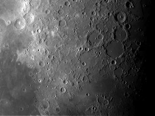
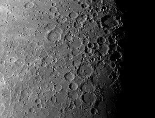
Image Gallery
Example images captured with G0 and G1 cameras.
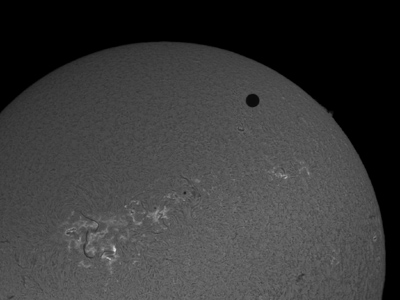 |
| Object |
Venus transit (H-alpha) |
| Author |
Martin Myslivec |
| Camera |
G1-2000 |
| Telescope |
Lunt LS60T |
|
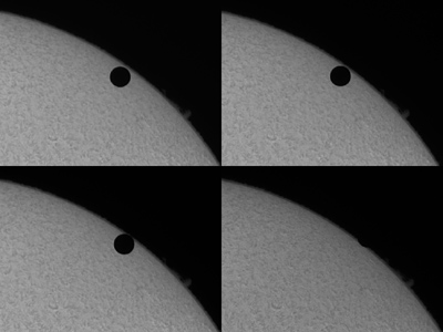 |
| Object |
Venus transit (H-alpha) |
| Author |
Martin Myslivec |
| Camera |
G1-2000 |
| Telescope |
Lunt LS60T |
|
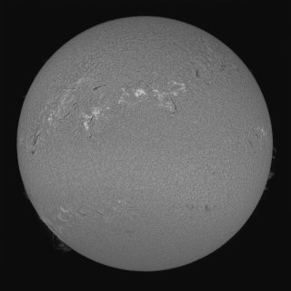 |
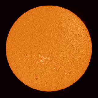
| Object |
Sun (H-alpha) |
| Author |
Martin Myslivec |
| Camera |
G1-2000 |
| Telescope |
Lunt LS60T |
|
 |
| Object |
Sun (H-alpha) |
| Author |
Martin Myslivec |
| Camera |
G1-2000 |
| Telescope |
Lunt LS60T |
|
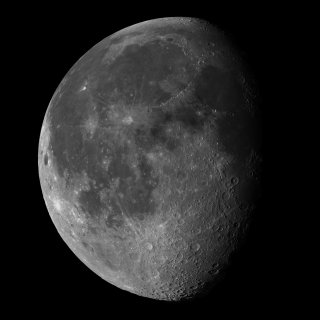 |
| Object |
Moon (mosaic) |
| Author |
Martin Myslivec |
| Camera |
G1-2000 |
| Telescope |
Vixen VC200L |
|
 |
| Object |
Moon (mosaic) |
| Author |
Martin Myslivec |
| Camera |
G1-2000 |
| Telescope |
Vixen VC200L |
|
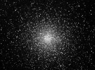 |
| Object |
47 Tucane |
| Author |
Steve Massey |
| Camera |
G1-0300 |
|
 |
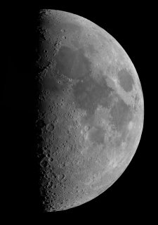
| Object |
Moon |
| Author |
Steve Massey |
| Camera |
G1-0300 |
|
 |
| Object |
Moon |
| Author |
Steve Massey |
| Camera |
G1-0300 |
|
All images published with permission of their respective
authors.
| 