|
G3 cameras can contain OnSemi KAF Full-Frame CCD detectors
as well as KAI Interline Transfer ones.
OnSemi KAF CCDs without ABG (Anti-Blooming Gate) offer linear
response to light are suitable for scientific applications. Large
area detectors with large pixels fit well to long focal length of
professional observatory telescopes. Large pixels enhance image
dynamic range. OnSemi KAF CCDs with ABG can be used both for research
applications and also for astrophotography. Anti-blooming ensures
round shapes of bright stars, while the Full-Frame architecture
provide clean and uniform frames without artifacts. OnSemi KAI detectors with ABG and electronic shutter could be
used for astrophotography. Anti-blooming ensures round shapes of
bright stars, which cannot be avoided especially on wide field
images.
No matter if your target is reliable scientific data or beautiful
images of deep-sky objects, G3 cameras are able to provide both.
G3 Camera Overview
G3 camera head is designed to be easily used with a set
of accessories to fulfill various observing needs. Camera head
itself is manufactured in two different variants:
Camera with internal filter wheel for five 2" or
D50 mm unmounted filters. Camera with control port for external filter wheel. This
model allows attachment of the external filter wheel for seven
2" or D50 mm unmounted
filters.
Camera head and numerous accessories comprise imaging system,
capable to be tailored for many applications.
G3 camera head with internal filter wheel G3 camera head capable to control External Filter
Wheel External Filter Wheel “S” size (7 positions) External Filter Wheel “L” size (9 or 7
positions) G0 Guider camera G1 Guider camera Off-Axis Guider with M68 × 1
thread Spacer compensating IFW and EFW back focal
distance 1.75” dovetail rail for G3 camera head Gx Camera Ethernet Adapter (x86 CPU) Gx Camera Ethernet Adapter (ARM CPU) 5-positions internal filter wheel for 2”/D50 mm
filters 7-positions external filter wheel “S” for 2”/D50 mm
filters 9-positions external filter wheel “L” for 2”/D50 mm
filters 7-positions external filter wheel “L” for 50 × 50 mm filters 2-inch barrel adapter T-thread (M42 × 0.75)
adapter Canon EOS bayonet adapter for Canon compatible
lenses Nikon bayonet adapter for Nikon compatible
lenses
G3 cameras are designed to work in cooperation with a
host Personal Computer (PC). As opposite to digital still
cameras, which are operated independently on the computer, the
scientific slow-scan, cooled cameras usually require computer
for operation control, image download, processing and storage
etc. To operate G3 camera, you need a computer which:
Is compatible with a PC standard. Runs a modern 32-bit or 64-bit Windows operating
system. Provides at last one free USB port. Alternatively it is possible to use the Gx Camera
Ethernet Adapter. This device can connect up to four Gx cameras
of any type (not only G3, but also G0, G1, G2 and G4) and offers
1 Gbps and 10/100 Mbps Ethernet interface for direct connection
to the host PC. Because the PC then uses TCP/IP protocol to
communicate with the cameras, it is possible to insert e.g. WiFi
bridge or other networking device to the communication
path.
G3 Camera Models
G3 series contains the following camera models:
| Model |
Color mask |
ABG |
CCD chip |
Resolution |
Pixel size |
Image area |
Download time |
| G3-01000 |
no |
no |
KAF-1001E |
1024 × 1024 |
24 × 24 μm |
24.6 × 24.6 mm |
~ 1.3 s |
| G3-06300 |
no |
no |
KAF-6303E |
3072 × 2048 |
9 × 9 μm |
27.7 × 18.4 mm |
~ 8 s |
| G3-16200 |
no |
2800× |
KAF-16200 |
4524 × 3624 |
6 × 6 μm |
27.2 × 21.8 mm |
~ 19 s |
| G3-16200C |
RGBG (Bayer) |
2800× |
KAF-16200 |
4524 × 3624 |
6 × 6 μm |
27.2 × 21.8 mm |
~ 19 s |
| G3-11000 |
no |
>1000× |
KAI-11002 |
4032 × 2688 |
9 × 9 μm |
36.3 × 24.2 mm |
~ 11 s |
| G3-11000C |
RGBG (Bayer) |
>1000× |
KAI-11002 |
4032 × 2688 |
9 × 9 μm |
36.3 × 24.2 mm |
~ 11 s |
G3 CCD Cameras Technical Specifications
CCD chip
G3 CCD cameras use OnSemi KAF Full Frame CCD detectors or
KAI Interline transfer CCD detectors with ABG and electronics
shutter. Advanced manufacturing technologies like transparent
electrodes and microlenses on the chip surface ensure high
quantum efficiency. The inherent dark current of these
detectors is very low compared to other scientific-grade CCDs,
so the resulting image S/N ratio is very good.

CCD detector with 24 × 36 mm area used in G3-11000
camera Model G3-1000
G3-1000 model uses 1 MPx OnSemi
KAF-1001E CCD.
| Resolution |
1024 (H) × 1024 (V)
pixels |
| Pixel size |
24 μm (H) × 24 μm (V) |
| Image area |
24.6 mm (H) × 24.6 mm (V) |
| Full well capacity |
~220,000 e- |
| Output node capacity |
~650,000 e- |
| Dark current |
17 e-/s/pixel at 0 °C |
| Dark signal doubling temperature |
5.5 °C |
KAF-1001E CCD specifications KAF-1001E CCD and its quantum
efficiency Model G3-6300
G3-6300 model uses 6 MPx OnSemi
KAF-6303E CCD.
| Resolution |
3072 (H) × 2048 (V)
pixels |
| Pixel size |
9 μm (H) × 9 μm (V) |
| Image area |
27.6 mm (H) × 18.4 mm (V) |
| Full well capacity |
~100,000 e- |
| Output node capacity |
~220,000 e- |
| Dark current |
1 e-/s/pixel at 0 °C |
| Dark signal doubling temperature |
6.3 °C |
KAF-6303E CCD specifications KAF-6303E CCD and its quantum
efficiency Model G3-16200
G3-16200 uses 16 MPx OnSemi KAF-16200 CCD with APS-H
format.
| Resolution |
4524 (H) × 3624 (V)
pixels |
| Pixel size |
6 μm (H) × 6 μm (V) |
| Image area |
27.2 mm (H) × 21.8 mm (V) |
| Full well capacity |
~41,000 e- |
| Dark current |
0.08 e-/s/pixel at
0 °C |
| Dark signal doubling temperature |
5.7 °C |
KAF-16200 CCD KAF-16200 CCD and its monochrome and color
quantum efficiency Model G3-11000
G3-11000 uses 11 MPx OnSemi KAI-11002
Class 1 or 2 CCD.
| Resolution |
4032 (H) × 2688 (V)
pixels |
| Pixel size |
9 μm
(H) × 9 μm (V) |
| Image area |
36.3 mm (H) × 24.2 mm (V) |
| Full well capacity |
~60,000 e- |
| Dark current |
12 e-/s/pixel at
0 °C |
| Dark signal doubling temperature |
7 °C |
KAI-11002 CCD KAI-11002 CCD and its quantum
efficiency Camera Electronics
16-bit A/D converter with correlated double sampling
ensures high dynamic range and CCD chip-limited readout noise.
Fast USB interface ensures image download time within
seconds.
Maximum length of single USB cable is 5 m. This length can be extended for instance
to 10 m by using single USB hub
or USB active extender cable. Up to 100 m extension can be achieved with
third-party extender.
Gx Camera Ethernet Adapter device allows connection of up
to four Gx cameras of any type through Ethernet interface and
TCP/IP network. Because TCP/IP protocol can be routed, the
distance between camera and host PC can be virtually
unlimited.
| ADC resolution |
16 bits |
| Sampling method |
Correlated double sampling |
| Read modes |
Preview |
| |
Low-noise |
| Horizontal binning |
1 to 4 pixels |
| Vertical binning |
1 to 4 pixels |
| Sub-frame readout |
Arbitrary sub-frame |
| Computer interface |
USB 2.0 High Speed |
| |
USB 1.1 Full Speed compatible |
Camera electronics specifications Image download time depends on the CCD chip used in
particular camera model. Also the read noise depends on the
chip as well as on the read mode.
Standard read mode provides system read noise approx.
1 e- above CCD chip read
noise. LN (Low-noise) read mode is somewhat slower (approx.
1.2×), but
ensures system read noise equal or smaller than the
manufacturer-specified chip read noise.
Model G3-1000
| Gain |
3 e-/ADU
(1 × 1 binning) |
| |
5 e-/ADU (other
binnings) |
| System read noise |
12 e- RMS (LN read) |
| |
15 e- RMS (standard
read) |
| Full frame download |
1.6 s (LN read) |
| |
1.3 s (standard read) |
G3-1000 electronics specification Model G3-6300
| Gain |
1.5 e-/ADU
(1 × 1 binning) |
| |
2.3 e-/ADU (other
binnings) |
| System read noise |
10 e- RMS (LN read) |
| |
12 e- RMS (standard
read) |
| Full frame download |
9.4 s (LN read) |
| |
7.3 s (standard read) |
G3-6300 electronics specification Model G3-16200
| Gain |
0.6 e-/ADU
(1 × 1 binning) |
| |
1.0 e-/ADU (other
binnings) |
| System read noise |
10 e- RMS (LN read) |
| |
11 e- RMS (standard
read) |
| Full frame download |
24.5 s (LN read) |
| |
18.8 s (standard read) |
G3-16200 electronics specification Model G3-11000
| Gain |
0.8 e-/ADU
(1 × 1 binning) |
| |
1.6 e-/ADU (other
binnings) |
| System read noise |
12 e- RMS (LN read) |
| |
14 e- RMS (standard
read) |
| Full frame download |
14.9 s (LN read) |
| |
11.2 s (standard read) |
G3-11000 electronics specification Notes:
Binning can be combined independently on both
axes LN read noise depends on the CCD chip itself. If the
read noise of the particular chip is 11.5
e- RMS, the system read noise is also
11.5 e- RMS. Download times can be somewhat longer when connected
to USB 1.1 host.

Power and USB connectors on the bottom of the
camera head Chip Cooling
Regulated thermoelectric cooling is capable to cool the CCD
chip from 45 to 50 °C below ambient temperature, depending on
the camera type. The Peltier hot side is cooled by a fans. The
CCD chip temperature is regulated with ±0.1 °C precision. High
temperature drop and precision regulation ensure very low dark
current for long exposures and allow proper image
calibration.
G3 cameras are available in two variants, differing
in the cooling performance:
Standard cooling cameras achieve temperature
difference up to 45 °C Under environment
temperature. Enhanced cooling cameras can regulate
temperature up to 50 °C under environment temperature.
Compared to standard variant, enhanced cooling cameras are
somewhat bulkier due to bigger heat sink, slightly heavier
and somewhat noisier because of more powerful fans.
| CCD chip cooling |
Thermoelectric (Peltier modules) |
| Standard cooling ΔT |
48 °C below ambient maximum |
| |
45 °C below ambient typical |
| Enhanced cooling ΔT |
53 °C below ambient maximum |
| |
50 °C below ambient typical |
| Regulation precision |
0.1 °C |
| Hot side cooling |
Air cooling (two fans) |
| |
Optional liquid coolant heat exchanger |
Chip cooling specifications  and enhanced (right) cooling cameras")
Comparison od the heat sink of standard (left) and
enhanced (right) cooling cameras Notes:
It is not recommended to cool the chip to the maximum
temperature difference, else the camera cannot guarantee
temperature stability when the ambient air temperature
rises. It is usually practical to set the temperature so the
cooling utilization varies around 90%. This provides enough
reserve in cooling power to keep the CCD temperature even if
the ambient temperature rises several degrees
Celsius. The cooling performance depends on the environmental
conditions and also on the power supply. If the power supply
voltage drops below 12 V, the
maximum temperature difference is lower.

Maximum temperature drop -50°C achieved with
approx. 75% cooling utilization Power supply
The 12 V DC power supply adapter enables camera
operation from arbitrary power source including batteries,
wall adapters etc. Universal 100–240 V AC/50–60 Hz,
60 W “brick” adapter is
supplied with the camera.
| Camera head supply |
12 V DC |
| Camera power consumption |
15 W without
cooling |
| |
52 W with 100%
cooling |
| Power connector |
5.5/2.5 mm, center + |
| Adapter input voltage |
100-240 V AC/50-60 Hz |
| Adapter output voltage |
12 V DC/5 A |
| Adapter maximum power |
60 W |
Power supply specifications Notes:
Camera power consumption is measured on the AC outlet
of the 12 V power
supply. The camera contains its own power supplies inside, so
it can be powered by unregulated 12 V DC power source — the input voltage can be anywhere between 10
and 14 V. However, some
parameters (like cooling efficiency) can degrade if the
supply drops below 12 V. G3 CCD camera measures its input voltage and provides
it to the control software. Input voltage is displayed in
the Cooling tab of the CCD Camera
control tool in the SIPS. This feature is important
especially if you power the camera from batteries.

12 V DC/5 A power
supply adapter for G3 Camera Warning: The power connector on the camera head uses
center-plus pin. Although all modern power supplies use this
configuration, always make sure the polarity is correct if you
use own power source. Mechanical Specifications
Compact and robust camera head measures only 154 × 154 × 65 mm
(approx. 6 × 6 × 2.6 inches).
A variant with internal filter wheel is thicker and measures
77.5 mm (approx.
3 inches). The head is CNC-machined from high-quality aluminum
and black anodized. The head itself contains USB-B (device)
connector and 12 V DC power plug, no other parts (CPU box, USB
interface, etc.), except a “brick” power supply, are
necessary. Integrated mechanical shutter allows streak-free
image readout, as well as automatic dark frame exposures,
which are necessary for unattended, robotic setups. Optional
integrated filter wheel contains 5 positions for standard
2" threaded filter cells with M48 × 0.75 thread or up to
50.8 mm “glass-only” filters.
G3 CCD camera with internal filter wheel
| Internal mechanical shutter |
Yes, blade shutter |
| Shortest exposure time |
0.2 s |
| Longest exposure time |
Limited by chip saturation only |
| Internal filter wheel (optional) |
5 positions for 2" threated cells
M48 × 0.75
or D50 mm
unmounted filters |
| Standard cooling head dimensions |
154 mm × 154 mm × 65 mm
(without filter wheel) |
| |
154 mm × 154 mm × 77.5 mm (with internal filter wheel) |
| Enhanced cooling head dimensions |
154 mm × 154 mm × 76 mm
(without filter wheel) |
| |
154 mm × 154 mm × 88.5 mm (with internal filter wheel) |
| Back focal distance |
16.5 mm (without filter wheel) |
| |
29 mm (with internal
filter wheel) |
| |
33.5 mm (with external filter wheel) |
| Standard cooling head weight |
1.6 kg
(without filter wheel) |
| |
1.9 kg
(with internal filter wheel) |
| |
2.5 kg
(with internal filter wheel) |
| Enhanced cooling head weight |
1.8 kg
(without filter wheel) |
| |
2.1 kg
(with internal filter wheel) |
| |
2.7 kg
(with internal filter wheel) |
Mechanical specifications Regardless if the camera has standard or enhanced cooling
or if it is equipped with internal filter wheel or not, the
front view dimensions are the same. Also mounting adapter
holes are the same, so both camera variants are compatible
with the same set of telescope/lens adapters.
The only different dimension is the camera thickness.
Enhanced cooling requires thicker camera back shell.

G3 camera head front view dimensions Dimensions of G3 camera with standard cooling and
internal filter wheel Dimensions of G3 camera with enhanced cooling and
internal filter wheel Variants without and with internal filter wheel have
different front shell thickness, which brings different Back
Focal Distance, but mechanical spacers, compensating for
different BFD are available (see the system diagram in the
“G3 Camera Overview” sub-chapter above).

G3 camera head with external filter wheel front
view dimensions Dimensions of G3 camera with standard cooling and
external filter wheel Dimensions of G3 camera with enhanced cooling and
external filter wheel Optional accessories
Camera head can be combined with various accessories according
to the requirements of the target application (optical system,
used filters, guiding, etc.).
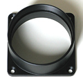
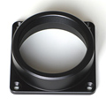
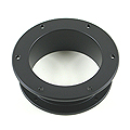
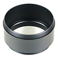
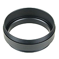
Telescope Adapters
Various telescope and lens adapters for the G3 cameras are
offered. Users can choose any adapter according to their needs
and another adapters can be ordered separately.
It is possible to choose from the following telescope/lens
adapters:
 |
| 2" barrel adapter |
| Adapter for 2" focusers. |
|
 |
| T-thread short |
| M42 × 0.75 inner
thread, 7.5 mm thick. |
|
 |
| T-thread with 55 mm
BFD |
| M42 × 0.75 inner
thread. |
| Preserves 55 mm back focal distance. |
|
 |
| M48 × 0.75 thread
short |
| M48 × 0.75 inner
thread, 7.5 mm thick. |
|
 |
| M48 × 0.75 thread
with 55 mm BFD |
| M48 × 0.75 inner
thread. |
| Preserves 55 mm back focal distance. |
|
 |
| Pentax (Praktica) lens adapter |
| M42 × 1 mm inner
thread. |
| Preserves 45.5 mm back focal distance. |
|
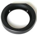 |
| M68 × 1 thread
adapter |
| Adapter with inner thread M68 × 1. |
|
 |
| Canon EOS lens adapter |
| Standard Canon EOS bayonet adapter. |
|
 |
| Nikon F lens adapter |
| Standard Nikon F bayonet adapter. |
|
 |
| 3” Wynne adapter |
| Adapter for 3” coma-corrector ASA Wynne. |
|
 |
| 3” Paracorr BIG adapter |
| Adapter for 3” coma-corrector TeleVue Paracorr BIG,
intended for attaching to EFW with M68×1. |
|
 |
| 3” Paracorr BIG adapter |
| Adapter for 3” coma-corrector TeleVue Paracorr BIG,
intended for G3-OAG. |
|
If the mounting standard defines also back focal distance
(distance from adapter front plane to detector), the
particular adapter is constructed to preserve defined distance
(for instance T-thread defines back focal distance to 55 mm,
but certain distance is defined also for Pentax (Praktica)
thread, for Canon EOS and Nikon bayonets etc.).
Adapters are attached to the camera body using four M3
(3 mm metric) screws. These threaded holes are placed on the
corners of 44 mm square. Custom adapters can be made upon
request.
External Filter Wheels
When there is no filter wheel inside the camera head, all
electronics and firmware, intended to control it, stays idle.
These components can be utilized to control external filter
wheel with only little changes. Also the camera front shell
can be manufactured thinner, the space for filter wheel is
superfluous.
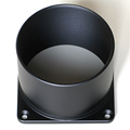
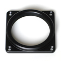
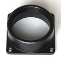
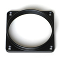
7-positions External Filter Wheel for the G3
camera External filter wheels are described in detail here.
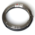
Off-Axis Guider adapter
The G3 off-axis guider (OAG) is designed to allow
attachment of any guiding camera with 1.25" eyepiece nose,
although the nose must be somewhat shorter to achieve focus.
G0 cameras are designed to achieve focus with G3 OAG and a
special shorter version of 1.25" nose with C-mount thread is
available for all G1 cameras. Any camera with CS-mount (short
version of C-mount standard) can use this adapter to be
attached to G3 OAG.
The G3 OAG offers the M68 × 1
thread on the telescope side. The back focal distance is
61.5 mm.
G3 Off-Axis Guider Adapters Off-Axis Guider adapters are described in detail here.
Guiding cameras
G0 and G1 cameras are completely independent devices with
their own USB connection to the host PC. They are mentioned
here only not to omit an important part of the whole
system.
G1-0301 standalone guiding/imaging camera is
equipped with USB connection and standard
“AutoGuider” port G0 and G1 cameras can be used on the G3 OAG, on standalone
guiding telescope or for any other imaging purpose, like Moon
or planetary imaging etc. Both G0 and G1 camera can share the
Gx Camera Ethernet Adapter with up to 3 other Gx cameras to be
accessed over network.
G0 and G1 guider cameras are described in detail here.
Attaching camera head to telescope mount
G3 cameras are equipped with two “tripod”
0.250-20UNC threads on the top side of the camera head. This
thread can be used to attach 1.75 inch “dovetail bar”
(Vixen standard). It is then possible to attach the camera
head, e.g. equipped with photographic lens, directly to
various telescope mounts supporting this standard.

1.75" bar for standard telescope mounts Spare desiccant containers
The G3 cameras are supplied with silicagel container,
intended to dry the CCD cold chamber. This container can be
unscrewed and desiccant inside can be dried in the owen (see
the camera User's Manual).
Container shipped with the camera by default does not
exceed the camera head outline. It is equipped with a slot for
tool (of for just a coin), allowing releasing and also
tightening of the container. Containers intended for enhanced
cooling cameras are prolonged as the camera thickness is
greater in the case of this variant.

Containers for standard and enhanced cooling
cameras also in variants allowing tool-less
manipulation It is possible to order spare container, which makes
desiccant replacement easier and faster. It is possible to dry
the spare container with silicagel and then only to replace it
on the camera. Spare container is supplied including the
air-tight cap.
Spare container can be supplied also in variant, allowing
manipulation without tools. But this container is longer and
exceeds camera outline. If the space behind the camera is not
critical, this container can make desiccant exchange even
easier.
Silicagel container with slot (left) and for
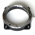
tool-less manipulation (right) Camera head color variants
Camera head is available in several color variants of the
center plate. Visit manufacturer's web pages for current
offering.
Gx Camera Ethernet Adapter
Gx Camera Ethernet Adapter allows connection of up to 4 Gx
cameras of any type on the one side and 1 Gbps Ethernet on the
other side. This adapter allows access to connected Gx cameras
using routable TCP/IP protocol over practically unlimited
distance.
The Gx Camera Ethernet Adapter is available in
several variants, but their functionality is basically the
same Gx Camera Ethernet Adapter devices are described in detail
here.
Software Support
Powerful SIPS (Scientific Image Processing System) software
supplied with the camera allows complete camera control
(exposures, cooling, filters) with automatic sequences and
complete image calibration. SIPS also supports advanced tools like
Image Add tool with automatic sub-pixel image alignment, (L)RGB
Add tool, Image Blink tool, image filters and many more
functions.
Scientific Image Processing System SIPS software package is freely available for download from this www site.
Drivers for ASCOM standard as well as native drivers for
third-party software are also available (e.g. TheSkyX, MaxIm DL,
AstroArt, etc.). Visit the download page of this web site for current list
of available drivers, please.
Automatic guiding
SIPS software package allows automatic guiding of the
astronomical telescope mounts using separate guiding camera.
Proper and reliable automatic guiding utilizing the
computational power of Personal Computer (e.g. calculation of
star centroid allows guiding with sub-pixel precision) is not
simple task. Guiding complexity corresponds to number of
parameters, which must be entered (or automatically
measured).

The SIPS “Guider” tool window The “Guiding” tool allows switching of autoguiding
on and off, starting of the automatic calibration procedure
and recalculation of autoguiding parameters when the telescope
changes declination without the necessity of new calibration.
Also swapping of the German Equatorial mount no longer
requires new autoguider calibration. There is also a graph
showing time history of guide star offsets from reference
position in both axes. The length of graph history as well as
the graph range can be freely defined, so the graph can be
adjusted according to particular mount errors and periodic
error period length. Complete log of calibration procedure,
detected offsets, correction pulses etc. is also shown in this
tool. The log can by anytime saved to log file.
An alternative to classic autoguiding is the inter-image
guiding, designed for modern mounts, which are precise enough
to keep tracking with sub-pixel precision through the single
exposure, and irregularities only appear on the
multiple-exposure time-span. Inter-image guiding then performs
slight mount position fixes between individual exposures of
the main camera, which eliminates “traveling” of the
observed objects through the detector area during observing
session. This guiding method uses main imaging camera, it does
not use another guiding camera and naturally does not need
neither OAG nor separate guiding telescope to feed the light
into it.

Inter-image guiding controls in the
Guiding tab of the Imager Camera tool
window Advanced reconstruction of color information of
single-shot-color cameras
Color CCD detectors have red, green and blue filters
applied directly on individual pixels (so-called Bayer
mask).
Schematic diagram of color CCD detector with Bayer
mask (left) and magnified crop of raw image captured by
color camera (right) Every pixel registers light of particular color only (red,
green or blue). But color image should contain all three
colors for every pixel. So it is necessary to calculate
missing information from values of neighboring pixels.
There are many ways how to calculate missing color
values — from simple extending of colors
to neighboring pixels (this method leads to coarse images with
visible color errors) to methods based on bi-linear or
bi-cubic interpolation to even more advanced multi-pass
methods etc.
Bi-linear interpolation provides significantly better
results than simple extending of color information to
neighboring pixels and still it is fast enough. But if the
telescope/lens resolution is close to the size of individual
pixels, color artifacts appear close to fine details, as
demonstrated by the image below left.
The above raw image with colors calculated using
bi-linear interpolation (left) and the same raw image, but
now processed by the multi-pass de-mosaic algorithm
(right) Multi-pass algorithm is significantly slower compared to
single-pass bi-linear interpolation, but the resulting image
is much better, especially in fine details. This method allows
using of color camera resolution to its limits.
SIPS offers choosing of color image interpolation method in
both “Image Transform” and “New Image Transform”
tools. For fast image previews or if the smallest details are
significantly bigger than is the pixel size (be it due to
seeing or resolution of the used telescope/lens) the fast
bi-linear interpolation is good enough. But the best results
can be achieved using multi-pass method.
Shipping and Packaging
G3 CCD cameras are supplied in the foam-filled, hard
carrying case containing:
Camera body with a user-chosen telescope adapter. The
standard 2" barrel adapter is included by default. If ordered,
the filter wheel is already mounted inside the camera head and
filters are threaded into place (if ordered). A 100-240 V AC input, 12 V DC output
“brick” adapter with 1.8 m
long power cable. 5 m long USB A-B cable for
connecting camera to host PC. USB Flash Drive or CD-ROM with camera drivers, SIPS
software package with electronic documentation and PDF version
of User's Manual. A printed copy of User's Manual.
G3 and G4 CCD cameras are shipped in the foam-filled
carrying case (left), larger case is used if camera is ordered
with external filter wheel (right) Image Gallery
Example images captured with G3 cameras.
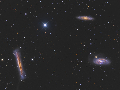
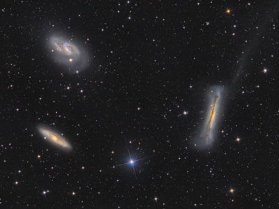 |
| Object |
M65, M66 a NGC 3628 “Leo Triplet” |
| Author |
Martin Myslivec |
| Camera |
G3-16200 |
| Filters |
LRGB |
| Exposure |
34 hours |
| Telescope |
300 mm, f/4
Newtonian telescope |
|
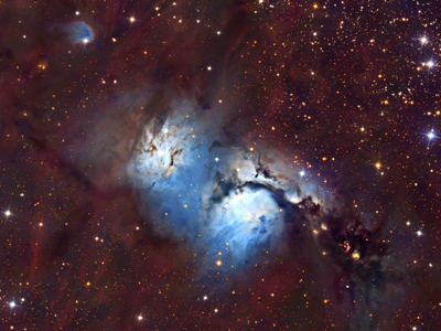 |
| Object |
M78 nebula |
| Author |
Martin Myslivec |
| Camera |
G3-16200 |
| Filters |
LRGB |
| Exposure |
39 hours |
| Telescope |
300 mm, f/4
Newtonian telescope |
|
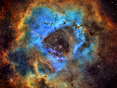 |
| Object |
NGC2237 “Rosette” |
| Author |
Martin Myslivec |
| Camera |
G3-16200 |
| Filters |
Hα, OIII, SII |
| Exposure |
31 hours |
| Telescope |
300 mm, f/4
Newtonian telescope |
|
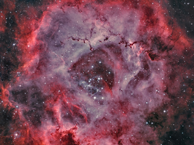 |
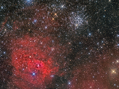
| Object |
NGC2237 “Rosette” |
| Author |
Martin Myslivec |
| Camera |
G3-16200 |
| Filters |
Hα, OIII (true
colors) |
| Exposure |
16 hours |
| Telescope |
300 mm, f/4
Newtonian telescope |
|
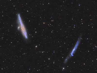 |
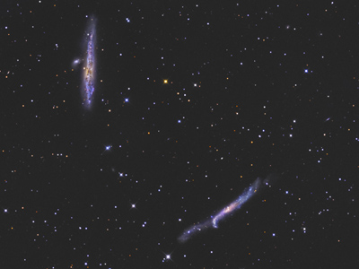
| Object |
NGC4631 “Whale Galaxy” and NGC4656 “Hockey Stick
Galaxy” |
| Author |
Martin Myslivec |
| Camera |
G3-16200 |
| Filters |
LRGB |
| Exposure |
26 hours |
| Telescope |
300 mm, f/4
Newtonian telescope |
|
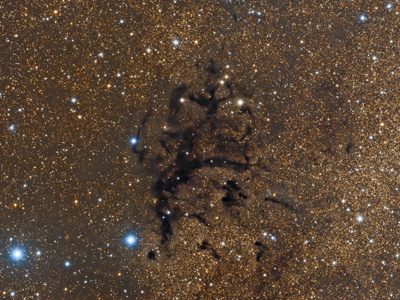 |
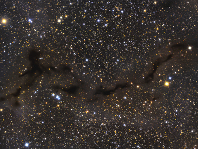
| Object |
LDN673 “Maya Glyph” dark nebula |
| Author |
Leonardo Orazi |
| Camera |
G3-16200 |
| Filters |
LRGB |
| Exposure |
18.5 hours |
| Telescope |
FSQ-106EDXIII |
|
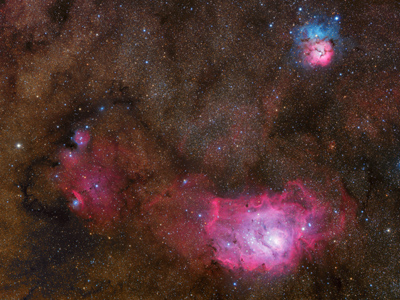 |
| Object |
M8 “Lagoon” and M20 “Trifid”
nebulae |
| Author |
Leonardo Orazi |
| Camera |
G3-16200 |
| Filters |
LRGB |
| Exposure |
27 hours |
| Telescope |
FSQ-106EDXIII |
|
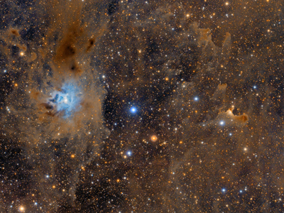 |
| Object |
NGC7023 “Iris” and VdB 141 “Ghost”
nebulae |
| Author |
Leonardo Orazi |
| Camera |
G3-16200 |
| Filters |
LRGB |
| Exposure |
22 hours |
| Telescope |
FSQ-106EDXIII |
|
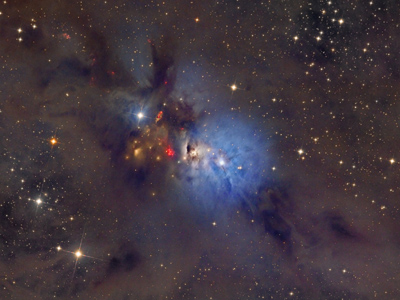 |
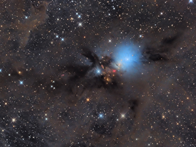
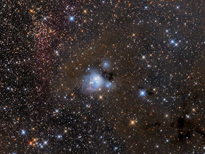
| Object |
NGC1333 |
| Author |
Martin Myslivec |
| Camera |
G3-16200 |
| Filters |
LRGB |
| Exposure |
39 hours |
| Telescope |
300 mm, f/4
Newtonian telescope |
|
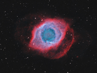 |
| Object |
NGC7293 “Helix” |
| Author |
Martin Myslivec |
| Camera |
G3-16200 |
| Filters |
HαOIII |
| Exposure |
45 hours |
| Telescope |
300 mm, f/4
Newtonian telescope |
|
 |
| Object |
NGC7635 “Bubble” nebula and M52
cluster |
| Author |
Ron Brecher |
| Camera |
G3-16200 |
| Filters |
HαRGB |
| Exposure |
21 hours |
| Telescope |
10” f/3.6 ASA astrograph |
|
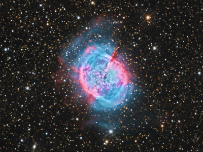 |
| Object |
M27 “Dumbbell” nebula |
| Author |
Ron Brecher |
| Camera |
G3-16200 |
| Filters |
RGB |
| Exposure |
12 hours |
| Telescope |
10” f/3.6 ASA astrograph |
|
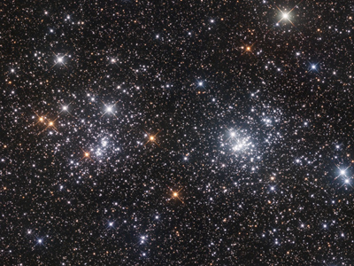 |
| Object |
χ a h double cluster in
Perseus |
| Author |
Ron Brecher |
| Camera |
G3-16200 |
| Filters |
RGB |
| Exposure |
1 hour |
| Telescope |
10” f/3.6 ASA astrograph |
|
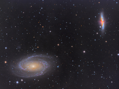 |
| Object |
M81 “Bode” and M82 “Cigar”
galaxies |
| Author |
Ram Viswanathan |
| Camera |
G3-16200 |
| Filters |
RGB |
| Exposure |
2 hours |
| Telescope |
TEC ADL300 |
|
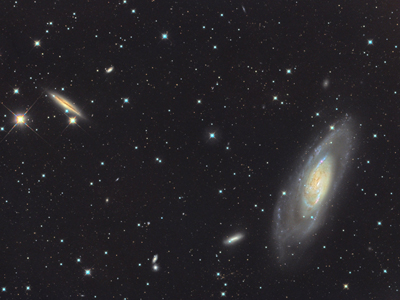 |
| Object |
M106 |
| Author |
Ram Viswanathan |
| Camera |
G3-16200 |
| Filters |
LRGB |
| Exposure |
4.5 hours |
| Telescope |
TEC ADL300 |
|
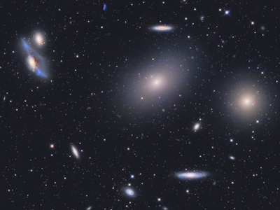 |
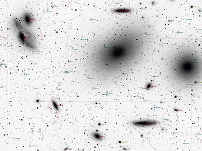
| Object |
Markarian chan of galaxies |
| Author |
Martin Myslivec |
| Camera |
G3-16200 |
| Filters |
LRGB |
| Exposure |
25 hours |
| Telescope |
300 mm, f/4
Newtonian telescope |
|
 |
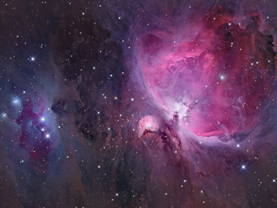 |
| Object |
M42 “Great Orion nebula” |
| Author |
Martin Myslivec |
| Camera |
G3-16200 |
| Filters |
LRGB |
| Exposure |
~3 hours |
| Telescope |
300 mm, f/4
Newtonian telescope |
|
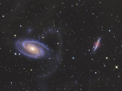 |
| Object |
M81 “Bode” and M82 “Cigar”
galaxies |
| Author |
Marco Burali |
| Camera |
G3-16200 |
| Filters |
LRGB |
| Exposure |
6 hours |
| Telescope |
Takahashi BRC 250, f/5 |
|
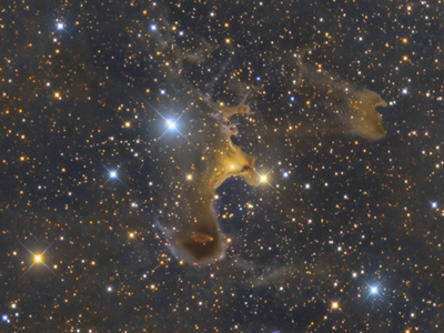 |
| Object |
VdB 141 “Ghost nebula” |
| Author |
Marco Burali |
| Camera |
G3-16200 |
| Filters |
LRGB |
| Exposure |
5 hours |
| Telescope |
Takahashi BRC 250, f/5 |
|
 |
| Object |
B150 dark nebula |
| Author |
Marco Burali |
| Camera |
G3-16200 |
| Filters |
LRGB |
| Exposure |
5 hours |
| Telescope |
Takahashi BRC 250, f/5 |
|
 |
| Object |
M65, M66 a NGC 3628 “Leo Triplet” |
| Author |
Marco Burali |
| Camera |
G3-16200 |
| Filters |
LRGB |
| Exposure |
6 hours |
| Telescope |
Takahashi BRC 250, f/5 |
|
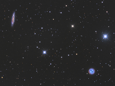 |
| Object |
M109, M97 “Owl nebula” |
| Author |
Marco Burali |
| Camera |
G3-16200 |
| Filters |
LRGB |
| Exposure |
5 hours |
| Telescope |
Takahashi BRC 250, f/5 |
|
 |
| Object |
NGC4631, NGC4656 |
| Author |
Marco Burali |
| Camera |
G3-16200 |
| Filters |
LRGB |
| Exposure |
7 hours |
| Telescope |
Takahashi BRC 250, f/5 |
|
 |
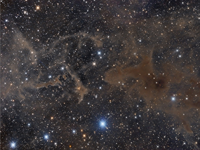
| Object |
NGC1333 |
| Author |
Pavel Pech |
| Camera |
G3-11000 |
| Filters |
Astrodon Tru-Balance I-Series LRGB + Halpha |
| Telescope |
ASA 10" N + ASA 3" Wynne corrector |
| Exposure |
12 hours |
|
 |
| Object |
LBN552 |
| Author |
Pavel Pech |
| Camera |
G3-11000 |
| Filters |
Astrodon Tru-Balance I-Series LRGB |
| Telescope |
ASA 10" N + ASA 3" Wynne corrector |
| Exposure |
8 hours |
|
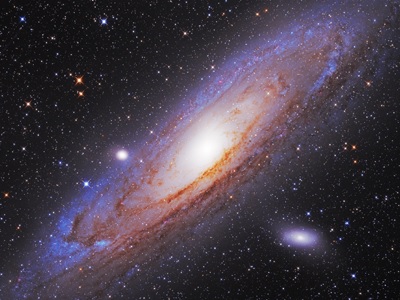 |
| Object |
M31 Andromeda galaxy |
| Author |
Pavel Pech |
| Camera |
G3-11000 |
| Filters |
Astrodon Tru-Balance I-Series LRGB + Halpha |
| Telescope |
ASA 10" N + ASA 3" Wynne corrector |
| Exposure |
5 hours |
|
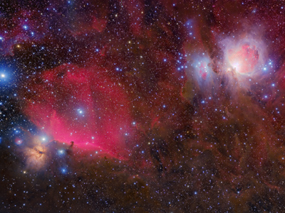 |
| Object |
Three nebulae in Orion: “Flame”, “Horse
Head” and “Great Nebula” |
| Author |
Pavel Pech |
| Camera |
G3-11000 |
| Filters |
Astrodon Tru-Balance I-Series LRGB + Halpha |
| Telescope |
Borg 77EDII + F4 ED Super Reducer |
| Exposure |
11 hours |
|
 |
| Object |
NGC7129 reflection nebula in Cepheus |
| Author |
Pavel Pech |
| Camera |
G3-11000 |
| Telescope |
ASA 10" f/3.6 Newton |
|
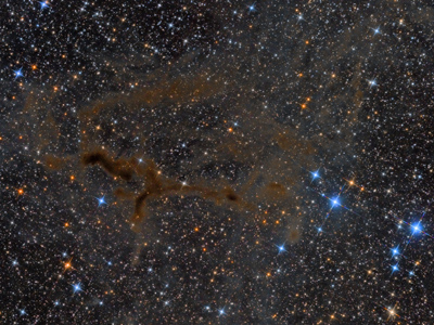 |
| Object |
LBN 603 dark nebula |
| Author |
Pavel Pech |
| Camera |
G3-11000 |
| Telescope |
ASA 10" f/3.6 Newton |
|
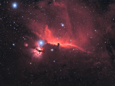 |
| Object |
“Hoese head” and “Flame” nebulae in
Orion (H-alpha + OIII) |
| Author |
Jonas Fiedler |
| Camera |
G3-11000 |
| Telescope |
Takahashi FSQ 106 |
|
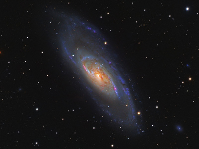 |
| Object |
M106 (H-alpha + LRGB) |
| Author |
Pavel Pech |
| Camera |
G3-11000 |
| Telescope |
Celestron C11 Edge HD |
|
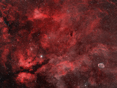 |
| Object |
Sard region in Cygnus (bi-color H-alpha a
OIII) |
| Author |
Pavel Pech |
| Camera |
G3-11000 |
| Telescope |
Borg 77EDII + Borg F4 ED Super Reducer |
|
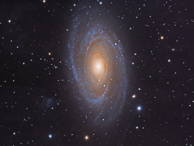 |
| Object |
M81 “Boode galaxy” |
| Author |
Pavel Pech |
| Camera |
G3-11000 |
| Telescope |
Celestron Edge HD 11 |
|
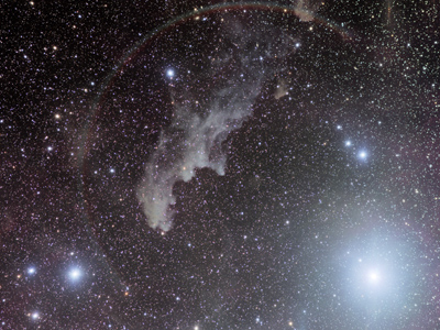 |
| Object |
“Witch head” nebula and Rigel |
| Author |
Pavel Pech |
| Camera |
G3-11000 |
| Telescope |
Borg 77EDII + F4 ED Super Reducer |
|
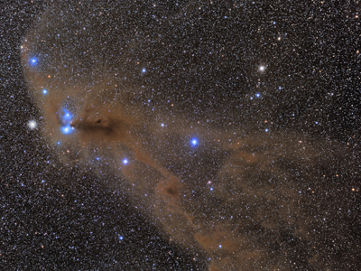 |
| Object |
Corona Australis |
| Author |
Pavel Pech |
| Camera |
G3-11000 |
| Telescope |
Borg 77EDII + F4 ED Super Reducer |
|
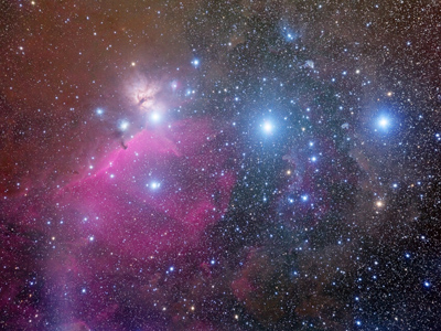 |
| Object |
Orion belt and “Horse head” nebula |
| Author |
Pavel Pech |
| Camera |
G3-11000 |
| Telescope |
Borg 77EDII + F4 ED Super Reducer |
|
All images published with permission of their respective
authors.
|