|
G4 cameras contain Full-Frame CCD chips OnSemi KAF with
36 × 36 mm detector area. These detectors
are equipped with so-called “anti-blooming gate” (ABG), which
drains the over-abundant charge from saturated pixels. ABG ensures the
round images of bright stars, without disruptive blooming spikes. On
the other side, compromising of the CCD linearity by ABG is only
negligible. G4 cameras can be used for astrometric and photometric
applications as well as for astrophotography.
No matter if your target is reliable scientific data or beautiful
images of deep-sky objects, G4 CCD cameras are able to provide
both.

G4-16000 CCD camera head G4 series contains the following camera models:
| Model |
Color mask |
CCD chip |
Resolution |
Pixel size |
Image area |
Download time |
| G4-9000 |
no |
KAF-09000 |
3056 × 3056 |
12 × 12 μm |
36.7 × 36.7 mm |
~ 12.5 s |
| G4-16000 |
no |
KAF-16803 |
4096 × 4096 |
9 × 9 μm |
36.9 × 36.9 mm |
~ 22 s |
G4 CCD cameras are designed to work in cooperation with a
host Personal Computer (PC). As opposite to digital still cameras,
which are operated independently on the computer, the scientific
slow-scan, cooled cameras usually require computer for operation
control, image download, processing and storage etc. To operate G4
CCD camera, you need a computer which:
Is compatible with a PC standard. Runs a modern 32 or 64 bit Windows operating system. Provides at last one free USB port.
G4 CCD Cameras Technical Specifications
CCD chip
G4 cameras use OnSemi Full-Frame CCD detectors with ABG
(anti-blooming gate), ensuring images without excessive charge
leaks from the overexposed portions of the image (blooming),
e.g. bright stars in the field of view. ABG of these CCDs is
designed for relatively low light levels (100× of saturation signal, compared to e.g.
300× of saturation signal ABG
level of KAI-4022 CCD or 1000×
of saturation signal ABG level of KAF-8300 CCD, intended for
taking of images against sun etc.). Low ABG level does not to
disrupt linear response to light.
CCD chip with 4096 × 4096 pixels resolution and 36 × 36 mm area for G4-16000
camera Model G4-9000
G4-9000 model uses 9 MPx OnSemi
KAF-09000 CCD.
| Resolution |
3056 (H) × 3056 (V)
pixels |
| Pixel size |
12 μm (H) × 12 μm (V) |
| Image area |
36.7 mm (H) × 36.7 mm (V) |
| Full well capacity |
~110,000 e- |
| Dark current |
5 e-/s/pixel at 25 °C |
| Dark signal doubling temperature |
7 °C |
KAF-09000 CCD specifications KAF-09000 CCD and its quantum
efficiency Model G4-16000
G4-16000 uses 16 MPx OnSemi KAF-16803
CCD.
| Resolution |
4096 (H) × 4096 (V)
pixels |
| Pixel size |
9 μm
(H) × 9 μm (V) |
| Image area |
36.9 mm (H) × 36.9 mm (V) |
| Full well capacity |
~100,000 e- |
| Dark current |
3 e-/s/pixel at
25 °C |
| Dark signal doubling temperature |
6.3 °C |
KAF-16803 CCD specifications KAF-16803 CCD and its quantum
efficiency Camera Electronics
16-bit A/D converter with correlated double sampling
ensures high dynamic range and CCD chip-limited readout noise.
Fast USB interface ensures image download time within several
tens of seconds.
Maximum length of single USB cable is 5 m. This length can be extended for instance
to 10 m by using single USB hub
or USB active extender cable. Up to 100 m extension can be achieved with
third-party extender.
| ADC resolution |
16 bits |
| Sampling method |
Correlated double sampling |
| Read modes |
Standard (STD) |
| |
Low-noise (LN) |
| Horizontal binning |
1 to 4 pixels |
| Vertical binning |
1 to 4 pixels |
| Sub-frame readout |
Arbitrary sub-frame |
| Computer interface |
USB 2.0 High Speed |
| |
USB 1.1 Full Speed compatible |
Camera electronics specifications Image download time depends on the CCD chip used in
particular camera model. Also the read noise depends on the
chip as well as on the read mode.
Standard read mode provides system read noise approx.
1 e- above CCD chip read
noise. LN (Low-noise) read mode is somewhat slower (approx.
1.2×), but
ensures system read noise equal or smaller than the
manufacturer-specified chip read noise.
Model G4-9000
| Gain |
1.5 e-/ADU
(1 × 1 binning) |
| |
1.7 e-/ADU (other
binnings) |
| System read noise |
7 e- RMS (LN read) |
| |
8 e- RMS (standard
read) |
| Full frame download |
15.7 s (LN read) |
| |
10.9 s (standard read) |
G4-9000 electronics specification The gain in binning modes of G4-9000 cameras was
adjusted from 2.5 e-/ADU to 1.7 e-/ADU beginning with
system driver version 2.3 to utilize the full A/D
converter dynamic range, because particular detector
output node cannot pass higher output signal levels either
way.
Model G4-16000
| Gain |
1.6 e-/ADU (all
innings) |
| System read noise |
9 e- RMS (KN read) |
| |
10 e- RMS (standard
read) |
| Full frame download |
27.8 s (KN read) |
| |
19.2 s (standard read) |
G4-15000 electronics specification G4-16000 cameras use the same gain for unbind and
binned reading when used with system driver version 2.3
and higher. When older driver is used, stated gain 1.6
e-/ADU is used for 1×l binning only, while all other
binning use 2.7 e-/ADU. Gain setting was unified to
utilize the full A/D converter dynamic range, because
particular detector output node cannot pass higher output
signal levels either way.
Notes:
Binning can be combined independently on both
axes ULN read noise depends on the CCD chip itself. If the
read noise of the particular chip is 7.5
e- RMS, the system read noise is also
7.5 e- RMS. Download times can be somewhat longer when connected
to USB 1.1 host.

Power and USB connectors on the back side of the
camera head. External filter wheel connector in the
middle. Warning: External filter wheel connector on the camera head
is of RJ-45 type, which is commonly used for Ethernet network
interface. But the G4 camera is not equipped with Ethernet
interface, it cannot be directly connected to Local Area
Network. It is necessary to use embedded PC, which
communicates with camera over USB and provides data to clients
using TCP/IP (including WWW interface). Chip Cooling
Regulated two-stage thermo-electric chip cooling up to
40 °C below ambient temperature
with forced air cooling and 0.1 °C temperature precision ensure very low
dark current for long exposures.
| CCD chip cooling |
Thermoelectric (Peltier modules) |
| TEC modules |
Two stages |
| Max. delta T |
45 °C below ambient
maximum |
| |
40 °C below ambient
typical |
| Regulation precision |
0.1 °C |
| Hot side cooling |
Air cooling (two 50 mm
fans) |
| |
Alternatively liquid cooling exchanger can be
used |
Chip cooling specifications Air (left) and liquid (right) cooling of Peltier
hot side Notes:
It is not recommended to cool the chip to the maximum
temperature difference, else the camera cannot guarantee
temperature stability when the ambient air temperature
rises. It is usually practical to set the temperature so the
cooling utilization varies around 90%. This provides enough
reserve in cooling power to keep the CCD temperature even if
the ambient temperature rises several degrees
Celsius. The cooling performance depends on the environmental
conditions and also on the power supply. If the power supply
voltage drops below 12 V, the
maximum temperature difference is lower. Camera construction does not allow usage of both air
and liquid cooling. Combined cooling (air with the liquid
cooling option) is not available, because such cooling does
not work effectively enough with air only nor with water
only.
Power supply
The 12 V DC power supply adapter enables camera
operation from arbitrary power source including batteries,
wall adapters etc. Universal 100–240 V AC/50–60 Hz,
60 W “brick” adapter is
supplied with the camera. Although the camera power
consumption does not exceed 30 W,
the 60 W power supply ensures
noise-free operation.
| Camera head supply |
12 V DC |
| Camera power consumption |
14 W without
cooling |
| |
50 W with 100%
cooling |
| Adapter input voltage |
100-240 V AC/50-60 Hz |
| Adapter output voltage |
12 V DC/5 A |
| Adapter maximum power |
60 W |
Power supply specifications Notes:
Camera power consumption is measured on the AC outlet
(230 V/50 Hz) of the 12 V power supply. The camera contains its own power supplies inside, so
it can be powered by unregulated 12 V DC power source—the input voltage can be anywhere between 10
and 14 V. However, some
parameters (like cooling efficiency) can degrade if the
supply drops below 11 V. G4 CCD camera measures its input voltage and provides
it to the control software. Input voltage is displayed in
the Cooling tab of the CCD Camera
control tool in the SIPS. This feature is important
especially if you power the camera from batteries.

12 V DC/5 A power
supply adapter for G4 Camera Warning: The power connector on the camera head uses
center-plus pin. Although all modern power supplies use this
configuration, always make sure the polarity is correct if you
use own power source. Mechanical Specifications
Compact and robust camera head measures only 154 × 154 × 65 mm
(approx. 6 × 6 × 2.5 inches).
The head is CNC-machined from high-quality aluminum and black
anodized. The head itself contains USB-B (device) connector,
8-pin RJ45 connector for external filter wheel and
12 V DC power plug, no other parts (CPU box, USB
interface, etc.), except a “brick” power supply, are
necessary. Integrated mechanical shutter allows streak-free
image readout, as well as automatic dark frame exposures,
which are necessary for unattended, robotic setups.
Filter wheel if not integrated into camera head, it is
necessary to use external filter wheel with 5 positions for
50 × 50 mm square filters. This external filter
wheel is driven by the electronics already included into G4
camera head. Only single short 8-wire cable connects the
filter wheel with the camera head and no separate power or
communication cables are necessary for the external filter
wheel. Also software (camera drivers, image acquisition
applications) does not distinguish between internal and
external filter wheel, camera works the same way like the G2
or G3 camera with integrated filter wheel.
| Internal mechanical shutter |
Yes, blade shutter |
| Shortest exposure time |
200 ms |
| Longest exposure time |
Limited by chip saturation only |
| Internal filter wheel |
no |
| Head dimensions |
154 mm × 154 mm × 65 mm |
| Back focal distance |
16.5 mm (without filter wheel) |
| |
33.5 mm (with external filter wheel) |
| Weight of camera head |
1.6 kg
(without filter wheel) |
| |
2.5 kg
(with “M” external filter wheel) |
| |
2.8 kg
(with “L” external filter wheel) |
Mechanical specification Notes:
Back focal distance is “optical”, which means
it calculates with refraction on the plan-parallel glass
optical elements in the light path.
Mechanical dimensions and back focal distance of
the G4 camera head Optional accessories
Camera head can be combined with various accessories according
to the requirements of the target application (optical system,
used filters, guiding, etc.).
Telescope adapters
Large diagonal dimension of CCD detectors used in G4
cameras (52 mm) does not allow
usage of common adapters, typically limited to 2 inches
diameter (50.8 mm), like T-thread M42 × 0.75, M48 × 1 thread, Nikon bayonet etc. This is why
G4 cameras are by default shipped with M68 × 1 threaded adapter.
Another alternative if Canon EOS photographic lens adapter,
which has enough diameter not to cause significant vignetting.
Adapter is designed for G4 cameras with external filter wheel,
with which it keep the 44 mm back
focal distance between bayonet front plate and CCD
detector.
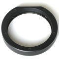 |
| M68 × 1 thread
adapter |
| Adapter with inner thread M68 × 1. |
|
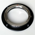 |
| Canon EOS lens adapter |
| Standard Canon EOS bayonet adapter. |
|
External Filter Wheels
Because large detectors if the G4 camera require
large 50 × 50 mm filters, filter wheel cannot be placed
inside the camera head and G4 cameras rely on external
filter wheels only. There are two sizes of external filter
wheels for G4 cameras available:
“M” (5-positions) and “L”
(7-positions) External Filter Wheels for the G4
camera External filter wheels for 5 filters 50 × 50 mm
(left) and for 7 filters D50 mm
or with M48 × 0.75 threaded cells
(right) External filter wheels are described in detail here.
Off-Axis Guider adapter
The G4 off-axis guider (OAG) is designed to allow
attachment of any guiding camera with 1.25" eyepiece nose,
although the nose must be somewhat shorter to achieve focus.
G0 cameras are designed to achieve focus with G4 OAG and a
special shorter version of 1.25" nose with C-mount thread is
available for all G1 cameras. Any camera with CS-mount (short
version of C-mount standard) can use this adapter to be
attached to G4 OAG.
The G4 OAG offers the M68 × 1
thread on the telescope side. The back focal distance is
61.5 mm.
G4 Off-Axis Guider Adapter Off-Axis Guider adapters are described in detail here.
Guiding cameras
G0 and G1 cameras are completely independent devices with
their own USB connection to the host PC. They are mentioned
here only not to omit an important part of the whole
system.
G1-0301 standalone guiding/imaging camera is
equipped with USB connection and standard
“AutoGuider” port G0 and G1 cameras can be used on the G4 OAG, on standalone
guiding telescope or for any other imaging purpose, like Moon
or planetary imaging etc. Both G0 and G1 camera can share the
Gx Camera Ethernet Adapter with up to 3 other Gx cameras to be
accessed over network.
G0 and G1 guider cameras are described in detail here.
Gx Camera Ethernet Adapter
Gx Camera Ethernet Adapter allows connection of up to 4 Gx
cameras of any type on the one side and 1 Gbps Ethernet on the
other side. This adapter allows access to connected Gx cameras
using routable TCP/IP protocol over practically unlimited
distance.
The Gx Camera Ethernet Adapter is available in
several variants, but their functionality is basically the
same Gx Camera Ethernet Adapter devices are described in detail
here.
Software Support
Powerful SIPS (Scientific Image Processing System) software
supplied with the camera allows complete camera control
(exposures, cooling, filters) with automatic sequences and
complete image calibration. SIPS also supports advanced tools like
Image Add tool with automatic sub-pixel image alignment, (L)RGB
Add tool, Image Blink tool, image filters and many more
functions.
Scientific Image Processing System SIPS software package is freely available for download from this www site.
Drivers for ASCOM standard as well as native drivers for
third-party software are also available (e.g. TheSkyX, MaxIm DL,
AstroArt, etc.). Visit the download page of this web site for current list
of available drivers, please.
Automatic guiding
SIPS software package allows automatic guiding of the
astronomical telescope mounts using separate guiding camera.
Proper and reliable automatic guiding utilizing the
computational power of Personal Computer (e.g. calculation of
star centroid allows guiding with sub-pixel precision) is not
simple task. Guiding complexity corresponds to number of
parameters, which must be entered (or automatically
measured).

The SIPS “Guider” tool window The “Guiding” tool allows switching of autoguiding
on and off, starting of the automatic calibration procedure
and recalculation of autoguiding parameters when the telescope
changes declination without the necessity of new calibration.
Also swapping of the German Equatorial mount no longer
requires new autoguider calibration. There is also a graph
showing time history of guide star offsets from reference
position in both axes. The length of graph history as well as
the graph range can be freely defined, so the graph can be
adjusted according to particular mount errors and periodic
error period length. Complete log of calibration procedure,
detected offsets, correction pulses etc. is also shown in this
tool. The log can by anytime saved to log file.
An alternative to classic autoguiding is the inter-image
guiding, designed for modern mounts, which are precise enough
to keep tracking with sub-pixel precision through the single
exposure, and irregularities only appear on the
multiple-exposure time-span. Inter-image guiding then performs
slight mount position fixes between individual exposures of
the main camera, which eliminates “traveling” of the
observed objects through the detector area during observing
session. This guiding method uses main imaging camera, it does
not use another guiding camera and naturally does not need
neither OAG nor separate guiding telescope to feed the light
into it.

Inter-image guiding controls in the
Guiding tab of the Imager Camera tool
window Shipping and Packaging
G4 CCD cameras are supplied in the foam-filled, hard
carrying case containing:
Camera body with a user-chosen telescope adapter. The
M68 × 1 adapter is included by
default, Canon EOS adapter is available at additional
cost. A 100-240 V AC input, 12 V DC output
“brick” adapter with 1.8 m
long power cable. 5 m long USB A-B cable for
connecting camera to host PC. A CD-ROM with camera drivers, SIPS software package with
electronic documentation and PDF version of
User's Manual. A printed copy of camera User's Manual.
G3 and G4 CCD cameras are shipped in the foam-filled
carrying case (left), larger case is used if camera is ordered
with external filter wheel (right) Image Gallery
Example images captured with G4 cameras.
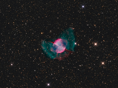 |
| Object |
M27 “Dumbbell” planetary nebula |
| Author |
Frédéric Lambert |
| Camera |
G4-16000 + EFW-L-7 |
| Filters |
RGB + narrow-band Hα,
OIII |
| Telescope |
Takahashi CCA 250 mm
f/5 |
|
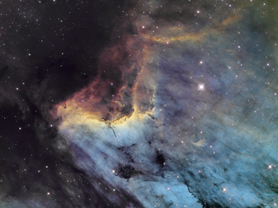 |
| Object |
IC5067 nebula |
| Author |
Frédéric Lambert |
| Camera |
G4-16000 + EFW-L-7 |
| Filters |
narrow-band Hα, SII,
OIII |
| Telescope |
Officina Stellare UCRC 300 |
|
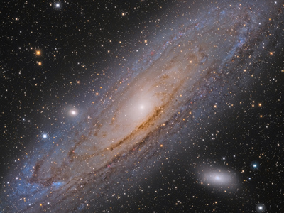 |
| Object |
M31 Big Andromeda Galaxy |
| Author |
Frédéric Lambert |
| Camera |
G4-16000 + EFW-L-7 |
| Filters |
RGB |
| Telescope |
Takahashi CCA 250 mm
f/5 |
|
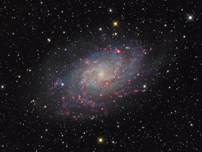 |
| Object |
M33 galaxy in Triangulum |
| Author |
Frédéric Lambert |
| Camera |
G4-16000 + EFW-L-7 |
| Filters |
RGB + narrow-band Hα |
| Telescope |
Takahashi CCA 250 mm
f/5 |
|
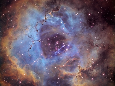 |
| Object |
NGC2244 “Rosette” nebula |
| Author |
Frédéric Lambert |
| Camera |
G4-16000 + EFW-L-7 |
| Filters |
narrow-band Hα, SII,
OIII |
| Telescope |
Officina Stellare UCRC 300 |
|
 |
| Object |
NGC6888 “Crescent” nebula |
| Author |
Frédéric Lambert |
| Camera |
G4-16000 + EFW-L-7 |
| Filters |
narrow-band Hα, SII |
| Telescope |
Officina Stellare UCRC 300 |
|
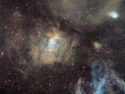 |
| Object |
NGC7635 “Bubble” nebula |
| Author |
Frédéric Lambert |
| Camera |
G4-16000 + EFW-L-7 |
| Filters |
narrow-band Hα, SII,
OIII |
| Telescope |
Takahashi CCA 250 mm
f/5 |
|
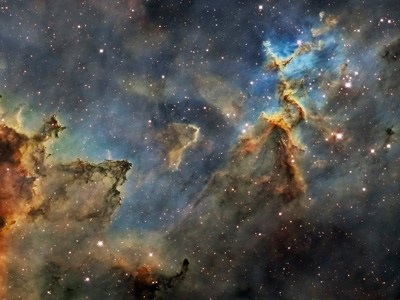 |
| Object |
IC1805 nebula |
| Author |
Laurent Bourgon |
| Camera |
G4-16000 + EFW-L-7 |
| Filters |
narrow-band Hα, SII,
OIII |
| Telescope |
Orion Optics/Skymeca 50 cm MDK f/6,8 |
|
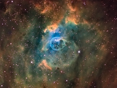 |
| Object |
NGC7635 “Bubble Nebula” in Cassiopeia |
| Author |
Laurent Bourgon |
| Camera |
G4-16000 + EFW-L-7 |
| Filters |
narrow-band Hα, SII,
OIII |
| Telescope |
Orion Optics/Skymeca 50 cm MDK f/6,8 |
|
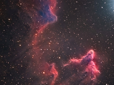 |
| Object |
IC63 nebula in Cassiopeia |
| Author |
Laurent Bourgon |
| Camera |
G4-16000 + EFW-L-7 |
| Filters |
LRGB |
| Telescope |
Orion Optics/Skymeca 50 cm MDK f/6,8 |
|
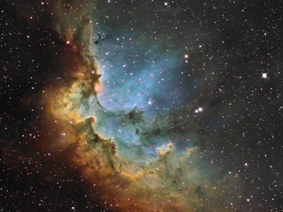 |
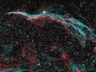
| Object |
NGC7380 “Wizadr Nebula” in Cepheus |
| Author |
Laurent Bourgon |
| Camera |
G4-16000 + EFW-L-7 |
| Filters |
narrow-band Hα, SII,
OIII |
| Telescope |
Orion Optics/Skymeca 50 cm MDK f/6,8 |
|
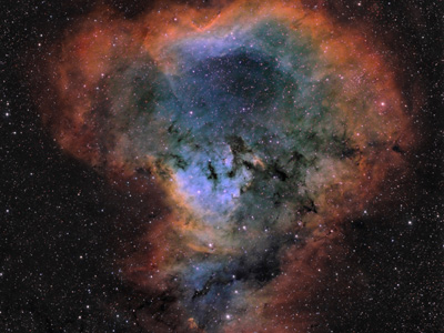 |
| Object |
NGC7822 star forming region in Cepheus |
| Author |
Laurent Bourgon |
| Camera |
G4-16000 + EFW-L-7 |
| Filters |
narrow-band Hα, SII,
OIII |
| Telescope |
FSQ106ed |
|
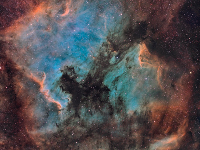 |
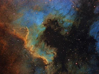
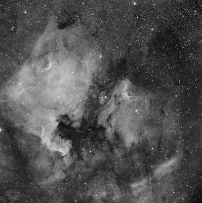
| Object |
“North America” and “Pelican”
nebulae |
| Author |
Laurent Bourgon and Didier Chaplain |
| Camera |
G4-16000 + EFW-L-7 |
| Filters |
narrow-band Hα, SII,
OIII a NII |
| Telescope |
FSQ106ed |
| Exposure |
65 hours |
|
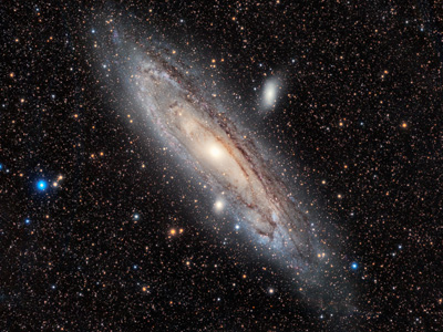 |
| Object |
M31 galaxy in Andromeda |
| Author |
Philippe Bernhard |
| Camera |
G4-16000 + EFW-L-7 |
| Filters |
LRGB |
| Telescope |
RH200 |
| Exposure |
3 hours |
|
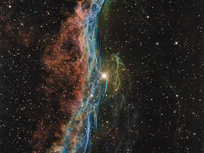 |
| Object |
NGC6960 “Veil” nebula |
| Author |
Laurent Bourgon |
| Camera |
G4-16000 + EFW-L-7 |
| Filters |
narrow-band Hα, SII a
OIII |
| Telescope |
Orion Optics/Skymeca 50 cm MDK f/6,8 |
|
 |
| Object |
NGC7000 mlhovina “Severní Amerika” |
| Author |
Michael Miller |
| Camera |
G4-16000 + EFW-L-7 |
| Filters |
narrow-band Hα, SII a
OIII |
| Telescope |
152mm APM APO |
|
 |
| Object |
NGC6960 “Veil” nebula |
| Author |
Michael Miller |
| Camera |
G4-16000 + EFW-L-7 |
| Filters |
Astrodon LRGB |
| Telescope |
152mm APM APO |
|
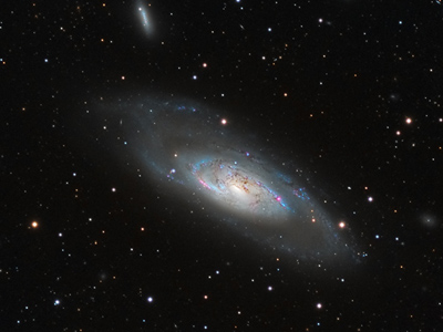 |
| Object |
M106 galaxy |
| Author |
Michael Miller, Warren Keller |
| Camera |
G4-16000 + EFW-L-7 |
| Filters |
Astrodon LRGB |
| Telescope |
152mm APM APO |
|
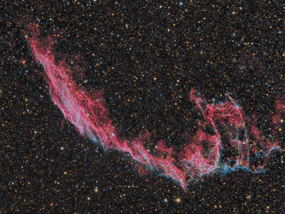 |
| Object |
NGC6992 “Veil nebula” |
| Author |
Michael Miller |
| Camera |
G4-16000 + EFW-L-7 |
| Filters |
Astrodon LRGB |
| Telescope |
152mm APM APO |
|
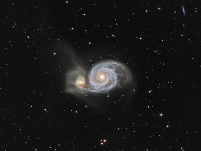 |
| Object |
M51 “Whirlpool” galaxy |
| Author |
Michael Miller |
| Camera |
G4-16000 + EFW-L-7 |
| Filters |
Astrodon LRGB |
| Telescope |
152mm APM APO |
|
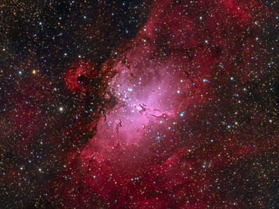 |
| Object |
M16 “Eagle” nebula |
| Author |
Michael Miller |
| Camera |
G4-16000 + EFW-L-7 |
| Filters |
Astrodon LRGB |
| Telescope |
152mm APM APO |
|
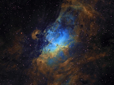 |
| Object |
M16 “Eagle” nebula |
| Author |
Michael Miller |
| Camera |
G4-16000 + EFW-L-7 |
| Filters |
H-alpha, OIII and SOII narrow-band |
| Telescope |
152mm APM APO |
|
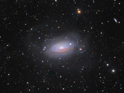 |
| Object |
M63 “Sunflower” galaxy |
| Author |
Michael Miller |
| Camera |
G4-16000 + EFW-L-7 |
| Filters |
Astrodon LRGB |
| Telescope |
152mm APM APO |
|
 |
| Object |
“North America” and “Pelican”
nebulae |
| Author |
Petr Novak |
| Camera |
G4-16000 + EFW4-5 |
| Filters |
12nm H-alfa |
| Telescope |
Takahashi FSQ 106 ED |
|
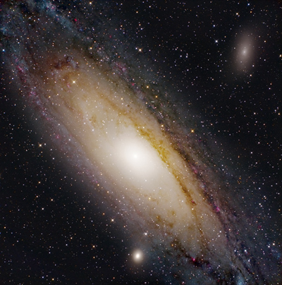 |
| Object |
M31 Great Andromeda Galaxy |
| Author |
Pavel Cagas (data acquisition), Martin Myslivec
(image registration) |
| Camera |
G4-16000 (cropped to 3k × 3k pixels) |
| Filters |
Astronomik LHaRGB |
| Telescope |
Orion SPX 250 + Paracorr |
|
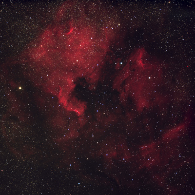 |
| Object |
“North America” and “Pelican”
nebulae |
| Author |
Martin Myslivec |
| Camera |
G4-16000 |
| Telescope |
Borg 66 ED |
|
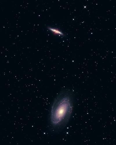 |
| Object |
M81 “Boode galaxy” and M82 “Cigar
galaxy” |
| Author |
Pavel Cagas |
| Camera |
G4-16000 (cropped to 3k × 3k pixels) |
| Filters |
Astronomik LHaRGB |
| Telescope |
Orion SPX 250 + Paracorr |
|
 |
| Object |
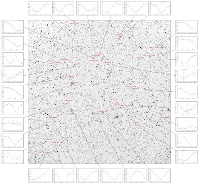
Field of variable star V729 Aql |
| Author |
Pavel Cagas, field composition Vaclav Pribik |
| Camera |
G4-16000 (cropped to 3k × 3k pixels) |
| Filters |
Clear |
| Telescope |
Orion SPX 250 + Paracorr |
|
All images published with permission of their respective
authors.
|