|
All members of the G2 Mark II series
of cooled CCD cameras are designed for low-light imaging applications,
requiring very high sensitivity and very low noise and dark current.
The G2 Mark II series comprises numerous model, each suitable for a
particular application area in astronomical research,
astro-photography, microscopy, life-sciences, material research
etc.
G2-0400, G2-1600 and G2-3200
models are equipped with Full-Frame, NABG detectors. Their features
make them especially suitable for research applications:
Very high sensitivity with peak QE above 80%. High full-well capacity (up to 100 ke- in the case of G2-0400 and G2-1600
models). Non-ABG detectors with perfectly linear response to
light.
G2-8300 still employs Full-Frame architecture CCD,
but thanks to ABG this particular model is especially popular among
astro-photographers:
KAF8300 CCD detector is equipped with anti-blooming gate
(ABG), which protects electron leaks from saturated pixels to
neighboring pixels when a bright star appears in the field of
view. Detector corresponds to the so-called “4/3 standard”
and its imaging area 18.1 × 13.7 mm is the largest of all
detectors used in the G2 series. High resolution (more than 8 MPx) and relatively small pixels
(5,4 × 5,4 μm)
makes this camera ideal for use with short focal length telescopes
(or with ordinary photographic lenses).
G2-2000 and G2-4000 models use
Interline-Transfer CCD detectors, bringing some unique
features:
Electronic shuttering allows very short exposures of bright
objects. Fast windowing allows reading of arbitrary detector sub-frame
faster than in the case of KAF CCD detectors. Anti-blooming gate ensures proper images of bright stars in
the field of view without blooming spikes, but it still does not
harm linearity, so these cameras can also be used for research
applications.
All members of the G2 Mark II series share the same design,
making them powerful research and imaging tools:
Top quality electronics:
Lowest possible read noise, limited by CCD detector
itself. Uniform frames without artifacts. High dynamic range, 16-bits digitization. Fast image download. Precise mechanical construction:
Compact camera head, small and lightweight enough to be
attached even to small telescopes. Integrated all-in-one design with USB and power
connectors directly on the camera head. Integrated mechanical shutter not to bother with covering
the telescope when taking dark frames. Optional integrated filter wheel. Telescope/lens adapters with adjustable tilt. Efficient and regulated sensor cooling:
CCD cooling up to 50 °C
below ambient temperature. Air cooling of the Peltier hot side with high quality
magnetic levitating fan. Cooling regulation +/-0.1 °C Single-voltage power supply enabling operation from
12V battery or “brick” adapter. Wide set of optional accessories:
External filter wheels supporting various number of
filter positions and filter sizes. Off-Axis Guider adapter. Various telescope/lens adapters (T-thread, M48,
Canon/Nikon bayonets etc.) Gigabit Ethernet adapter. Telescope mount dovetail adapter. Rich software support:
Drivers for 32bit and 64bit Windows Drivers for 32bit and 64bit Linux Drivers for macOS (only certain applications are
supported on macOS) Complete camera/observatory control and scientific image
processing system SIPS free with camera Drivers for 3rd party software packages, including
universal ASCOM drivers
No matter if your target is reliable scientific data or beautiful
images of deep-sky objects, G2 Mark II cameras are able to provide
both.
G2 Mark II Camera Overview
G2 camera head is designed to be easily used with a set
of accessories to fulfill various observing needs. Camera head
itself is manufactured in two different variants:
Camera with Internal filter wheel. Camera with control port for External filter wheel. This
model allows attachment of several variants of external filter
wheels with various number of filter positions and
sizes.
, with Internal filter wheel (middle) and with attached External filter wheel (right)")
G2 Camera Mark II without filter wheel (left), with
Internal filter wheel (middle) and with attached External filter
wheel (right) G2 camera model with Internal filter wheel accepts two
sizes of filters:
G2 Mark II camera with Internal filter wheel (left) and
with External filter wheel attached (right) There are two sizes of the External filter wheels, each
capable to accept multiple sizes of filters, available for the
G2 cameras:
Extra small “XS” size wheel for 8 unmounted
filters D31 mm or filters in 1.25”
threaded cells. Extra small “XS” size wheel for 7 unmounted
filters D36 mm. Small “S” size wheel for 12 unmounted filters
D31 mm or filters in 1.25” threaded
cells. Small “S” size wheel for 10 unmounted filters
D36 mm. Small “S” size wheel for 7 unmounted D50 mm or 2" filter or filters in 2” threaded
cells.
Warning: Please note the camera head is designed to either
accept Internal filter wheel or to be able to connect to the
External filter wheel, but not both. If the Internal filter wheel
variant is used, External filter wheel cannot be
attached. Components of G2 Mark II Camera system
include:
G2 camera head with Internal Filter Wheel (5 or 6
positions) G2 camera head capable to control External Filter
Wheel External Filter Wheel “XS” size (7 or 8
positions) External Filter Wheel “S” size (10 or 12
positions) G0 guider camera G1 guider camera Off-Axis Guider with M48 × 0.75 thread Off-Axis Guider with M42 × 0.75 thread (T2) Thick adapter base, compensating EFW thickness to achieve
proper back focal distance for cameras without filter
wheel 1.75” dovetail rail for G2 camera head Gx Camera Ethernet Adapter (x86 CPU) Gx Camera Ethernet Adapter (ARM CPU) 5-positions internal filter wheel for 1.25”/D31 mm
filters 8-positions external filter wheel “XS” for
1.25”/D31 mm filters 7-positions external filter wheel “XS” for D36 mm
filters 12-positions external filter wheel “S” for
1.25”/D31 mm filters 10-positions external filter wheel “S” for D36 mm
filters 7-positions external filter wheel “S” for 2”/D50
mm filters M42 × 0.75 (T-thread) or
M48 × 0.75 threaded adapters, 55 mm
BFD Canon EOS bayonet lens adapter Nikon bayonet lens adapter
The G2 cameras are designed to work in cooperation with
a host Personal Computer (PC). As opposite to digital still
cameras, which are operated independently on the computer, the
scientific slow-scan, cooled cameras usually require computer
for operation control, image download, processing and storage
etc. To operate the camera, you need a computer which:
Is compatible with a PC standard and runs modern 32 or
64-bit Windows operating system. Is compatible with a PC standard and runs 32 or 64-bit
Linux operating system. Support for x64 based Apple Macintosh computers is also
included.
G2 cameras require at last one free USB 2.0 port to communicate
with a host PC.
Alternatively, it is possible to use the Gx Camera Ethernet
Adapter device. This device can connect up to four Gx cameras
of any type (not only G2, but also G0, G1, G3 and G4) and offers 1
Gbps and 10/100 Mbps Ethernet interface for direct connection to
the host PC. Because the PC then uses TCP/IP protocol to
communicate with the cameras, it is possible to insert WiFi
adapter or other networking device to the communication path.
G2 Mark II Camera Models
Available models of G2 Mark II cameras:
| Model |
CCD Chip |
ABG |
Color mask |
Resolution |
Pixel size |
Imaging area |
Preview download |
Low-Noise download |
| G2-0400 |
KAF-0402ME |
No |
None |
768 × 512 |
9 × 9 μm |
6.9 × 4.6 mm |
0.19 s |
0.25 s |
| G2-1600 |
KAF-1603ME |
No |
None |
1536 × 1024 |
9 × 9 μm |
13.8 × 9.2 mm |
0.67 s |
0.95 s |
| G2-3200 |
KAF-3200ME |
No |
None |
2184 × 1472 |
6.8 × 6.8 μm |
14.9 × 10.0 mm |
1.39 s |
1.95 s |
| G2-8300 |
KAF8300 Monochrome |
>1000× |
None |
3358 × 2536 |
5.4 × 5.4 μm |
18.1 × 13.7 mm |
3.48 s |
4.95 s |
| G2-8300C |
KAF8300 Color |
>1000× |
Bayer RGBG |
3358 × 2536 |
5.4 × 5.4 μm |
18.1 × 13.7 mm |
3.48 s |
4.95 s |
| G2-2000 |
KAI-2020 Monochrome |
>300× |
None |
1604 × 1204 |
7.4 × 7.4 μm |
11.9 × 8.9 mm |
0.73 s |
1.06 s |
| G2-2000C |
KAI-2020 Color |
>300× |
Bayer RGBG |
1602 × 1202 |
7.4 × 7.4 μm |
11.9 × 8.9 mm |
0.73 s |
1.06 s |
| G2-4000 |
KAI-4022 Monochrome |
>300× |
None |
2056 × 2062 |
7.4 × 7.4 μm |
15.2 × 15.3 mm |
1.56 s |
2.30 s |
| G2-4000C |
KAI-4022 Color |
>300× |
Bayer RGBG |
2054 × 2060 |
7.4 × 7.4 μm |
15.2 × 15.3 mm |
1.56 s |
2.30 s |
CCD detectors
G2 Mark II series of CCD cameras are manufactured with
two kinds of CCD detectors:
G2 cameras with OnSemi KAF Full Frame (FF) CCD
architecture. Almost all Full Frame CCD detector area is
exposed to light. This is why these detectors provide very high
quantum efficiency. FF CCD detectors, intended for research
applications, are not equipped with so-called Anti Blooming Gate
(ABG – a gate, which prohibits blooming of the charge to
neighboring pixels when image is over-exposed) to ensure linear
response to light through the whole dynamic range. FF CCD
detectors used for astrophotography are equipped with ABG to
eliminate disrupting blooming streaks within field of
view. Cameras with Full Frame, non-ABG detectors are
suitable for scientific applications, where linear response is
necessary for photometric applications in astronomy, microscopy
etc. High quantum efficiency could be used also for narrow-band
imaging, where overexposure is a rare exception, and for imaging
of small objects without a bright star in the field of
view. 
“Full Frame” CCD schematic diagram G2 cameras with OnSemi KAI Interline Transfer (IT)
architecture. There is a shielded column of pixels just
beside each column of active pixels on these detectors. The
shielded columns are called Vertical registers. One pulse moves
charge from exposed pixels to shielded pixels on the end of each
exposure. The the charge is moved from vertical registers to
horizontal register and digitized in the same way like in the
case of Full Frame detectors. This mechanism is also known as
“electronic shuttering” because it allows very short exposures
and also digitization of the image without mechanically
shielding of the detector from incoming
light. The price for electronic shutter
if lower quantum efficiency (sensitivity) of IT detectors
compared to FF ones. Also, all IT detectors are equipped with
ABG, so they can acquire images of very bright objects without
charge blooming to neighboring pixels. 
“Interline Transfer” CCD schematic
diagram
Model G2-0400
G2-0400 model uses 0.4 MPx OnSemi
KAF-0402ME NABG Full-Frame CCD chip.
| Resolution |
768 (H) × 512 (V)
pixels |
| Pixel size |
9 μm (H) × 9 μm (V) |
| Imaging area |
6.9 mm
(H) × 4.6 mm (V) |
| Full well capacity |
~100,000 e- |
| Output node capacity |
~220,000 e- |
| Anti-blooming gate |
No |
| Dark current |
1 e-/s/pixel at 0 °C |
| Dark signal doubling temperature |
6.3 °C |
KAF-0402ME CCD chip specifications KAF-0402ME CCD chip and its Quantum
Efficiency Model G2-1600
G2-1600 model uses 1.6 MPx OnSemi
KAF-1603ME NABG Full-Frame CCD chip.
| Resolution |
1536 (H) × 1024 (V)
pixels |
| Pixel size |
9 μm (H) × 9 μm (V) |
| Imaging area |
13.8 mm (H) × 9.2 mm (V) |
| Full well capacity |
~100,000 e- |
| Output node capacity |
~220,000 e- |
| Anti-blooming gate |
No |
| Dark current |
1 e-/s/pixel at 0 °C |
| Dark signal doubling temperature |
6.3 °C |
KAF-1603ME CCD chip specifications KAF-1603ME CCD chip and its Quantum
Efficiency Model G2-3200
G2-3200 model uses 3.2 MPx OnSemi
KAF-3200ME NABG Full-Frame CCD chip.
| Resolution |
2184 (H) × 1472 (V)
pixels |
| Pixel size |
6.8 μm
(H) × 6.8 μm (V) |
| Imaging area |
14.9 mm (H) × 10 mm (V) |
| Full well capacity |
~55,000 e- |
| Output node capacity |
~110,000 e- |
| Anti-blooming gate |
No |
| Dark current |
0.8 e-/s/pixel at
0 °C |
| Dark signal doubling |
6 °C |
KAF-3200ME CCD chip specifications KAF-3200ME CCD chip and its Quantum
Efficiency Model G2-8300
G2-8300 camera uses 8 MPx OnSemi KAF8300 ABG Full Frame CCD
detectors with 4/3 format.
| Resolution |
3358 (H) × 2536 (V)
pixels |
| Pixel size |
5.4 μm
(H) × 5.4 μm (V) |
| Imaging area |
18.1 mm (H) × 13.7 mm (V) |
| Full well capacity |
~25,000
e-- |
| Anti-blooming gate |
1000× |
| Dark current |
0.2 e-/s/pixel at
0 °C |
| Dark signal doubling temperature |
5.8 °C |
KAF-0402ME CCD chip specifications KAF8300 CCD chip and its Quantum
Efficiency Model G2-2000
G2-2000 model uses 2 MPx OnSemi ABG
Inteline-Transfer KAI-2020 CCD chip.
| Resolution |
1604 (H) × 1204 (V)
pixels |
| Pixel size |
7.4 μm
(H) × 7.4 μm (V) |
| Imaging area |
11.9 mm (H) × 8.9 mm (V) |
| Full well capacity |
~40,000 e- |
| Anti-blooming gate |
300× |
| Dark current |
0.3 e-/s/pixel at
0 °C |
| Dark signal doubling |
7 °C |
KAI-2020 CCD chip specifications KAI-2020 CCD chip and its Quantum
Efficiency Model G2-4000
G2-4000 model uses 4 MPx OnSemi ABG
Inteline-Transfer KAI-4022 CCD chip.
| Resolution |
2056 (H) × 2062 (V)
pixels |
| Pixel size |
7.4 μm
(H) × 7.4 μm (V) |
| Imaging area |
15.2 × 15.3 mm |
| Full well capacity |
~40,000 e- |
| Anti-blooming gate |
300× |
| Dark current |
0.3 e-/s/pixel at
0 °C |
| Dark signal doubling |
7 °C |
KAI-4022 CCD chip specifications KAI-4022 CCD chip and its Quantum
Efficiency Camera Electronics
16-bit A/D converter with correlated double sampling ensures
high dynamic range and CCD chip-limited readout noise. Fast USB
interface ensures image download time within seconds.
Maximum length of single USB cable is approx. 5 m. This length
can be extended to 10 m or 15 m by using single USB hub or active
USB extender cable. Up to 5 hubs or active extenders can be used
in one connection.
Gx Camera Ethernet Adapter device allows connection of
up to four Gx cameras of any type through Ethernet interface and
TCP/IP network. Because TCP/IP protocol can be routed, the
distance between camera and host PC can be virtually
unlimited.
| ADC resolution |
16 bits |
| Sampling method |
Correlated double sampling |
| Read modes |
Preview mode |
| |
Low Noise mode |
| Horizontal binning |
1 to 4 pixels |
| Vertical binning |
1 to 4 pixels |
| Sub-frame readout |
Arbitrary sub-frame |
| Computer interface |
USB 2.0 High Speed |
| |
USB 1.1 Full Speed compatible |
Camera electronics specifications Image download time depends on the CCD chip used in
particular camera model. Also the read noise depends on the chip
as well as on the read mode.
Preview read mode provides system read noise
approx. 1 or 2 e- above
CCD chip read noise. Low Noise read mode is somewhat slower, but
ensures system read noise roughly equal to the
manufacturer-specified chip read noise.
Model G2-0400
| Gain |
1.5 e-/ADU (1 × 1 binning) |
| |
2.0 e-/ADU (other
binnings) |
| System read noise |
13 e- RMS (Low Noise mode) |
| |
15 e- RMS (Preview
mode) |
| Full frame download |
0.25 s (Low Noise mode) |
| |
0.16 s (Preview mode) |
G2-0400 electronics specifications Model G2-1600
| Gain |
1.5 e-/ADU (1 × 1 binning) |
| |
2.0 e-/ADU (other
binnings) |
| System read noise |
13 e- RMS (Low Noise mode) |
| |
15 e- RMS (Preview
mode) |
| Full frame download |
0.95 s (Low Noise mode) |
| |
0.67 s (Preview mode) |
G2-1600 electronics specifications Model G2-3200
| Gain |
0.8 e-/ADU (1 × 1 binning) |
| |
1.3 e-/ADU (other
binnings) |
| System read noise |
7 e- RMS (Low Noise mode) |
| |
9 e- RMS (Preview
mode) |
| Full frame download |
1.95 s (Low Noise mode) |
| |
1.39 s (Preview mode) |
G2-3200 electronics specifications Model G2-8300
| Gain |
0.4 e-/ADU (1 × 1 binning) |
| |
0.8 e-/ADU (other
binnings) |
| System read noise |
8 e- RMS (Low Noise mode) |
| |
9 e- RMS (Preview
mode) |
| Full frame download |
4.95 s (Low Noise mode) |
| |
3.48 s (Preview mode) |
G2-8300 electronics specifications Model G2-2000
| Gain |
0.5 e-/ADU (1 × 1 binning) |
| |
0.8 e-/ADU (other
binnings) |
| System read noise |
7 e- RMS (Low Noise
mode) |
| |
9 e- RMS (Preview
mode) |
| Full frame download |
1.06 s (Low Noise mode) |
| |
0.73 s (Preview mode) |
G2-2000 electronics specifications Model G2-4000
| Gain |
0.5 e-/ADU (1 × 1 binning) |
| |
0.8 e-/ADU (other
binnings) |
| System read noise |
7 e- RMS (Low Noise
mode) |
| |
9 e- RMS (Preview
mode) |
| Full frame download |
2.30 s (Low Noise mode) |
| |
1.56 s (Preview mode) |
G2-4000 electronics specifications Notes:
Binning can be combined independently on both
axes. Stated read noise is measured on particular CCD sensor,
evaluated during camera design. Actual read noise of different
sensors varies among various manufacturing batches, but also
within single manufacturing batch. The camera read noise is
determined by the sensor itself and the camera manufacturer
cannot affect it.
Cooling and power supply
Regulated thermoelectric cooling is capable to cool the CCD
chip up to 50 °C below ambient
temperature. The Peltier hot side is cooled by fan. The CCD chip
temperature is regulated with +/-0.1 °C precision. High temperature drop and
precision regulation ensure very low dark current for long
exposures and allow proper image calibration.
 and with internal filter wheel (right)")
Bottom side with connectors of the camera without
filter wheel (left) and with internal filter wheel
(right) The camera head contains two temperature sensors — the first sensor measures directly the temperature
of the CCD chip package. The second one measures the temperature
inside the camera shell.

Back side of the G2 Mark II camera head contains vents
for a fan, cooling Peltier hot side The cooling performance depends on the environmental conditions
and also on the power supply. If the power supply voltage drops
below 12 V, the maximum temperature
drop is lower.
| CCD chip cooling |
Thermoelectric (Peltier modules) |
| Maximal cooling Δ T |
>50 °C below
ambient |
| Regulated cooling Δ T |
45 °C below ambient (85%
cooling) |
| Regulation precision |
0.1 °C |
| Hot side cooling |
Forced air cooling (fan) |
Chip cooling specifications Power supply
The 12 V DC power supply enables camera operation
from arbitrary power source including batteries, wall adapters
etc. Universal 100-240 V
AC/50-60 Hz, 60 W “brick” adapter is supplied with
the camera. Although the camera power consumption does not
exceed 40 W, the 60 W power supply ensures noise-free
operation.
| Camera power supply |
12 V DC |
| Camera power consumption |
15 W without cooling |
| |
40 W maximum cooling |
| Power plug |
5.5/2.5 mm, center
+ |
| Adapter input voltage |
100-240 V AC/50-60 Hz |
| Adapter output voltage |
12 V DC/5 A |
| Adapter maximum power |
60 W |
Power supply specification Warning: The power connector on the camera head uses
center-plus pin. Although all modern power supplies use this
configuration, always make sure the polarity is correct if
other than the supplied power source is used. 
12 V DC/5 A power supply adapter for G2
camera Mechanical Specifications
Compact and robust camera head measures only 114 × 114 × 65 mm
(approx. 4.5 × 4.5 × 2.6 inches). The head is CNC-machined from
high-quality aluminum and black anodized. The head itself contains
USB-B (device) connector and 12 V DC power plug.
Integrated mechanical shutter allows streak-free image readout, as
well as automatic dark frame exposures, which are necessary for
unattended, robotic setups.
Bottom side of the camera without filter wheel (left)
and with internal filter wheel (right) Camera head with integrated Internal filter wheel is 77.5 mm
thick. Filter wheel offers 5 positions for standard 1.25-inch
threaded filter cells. A variant of filter wheel with 6 positions
for unmounted D26 mm filters is also
available.
| Internal mechanical shutter |
Yes, blade shutter |
| Shortest exposure time |
0.1 s |
| Longest exposure time |
Limited by chip saturation only |
| Internal filter wheel |
5 positions for 1.25" threaded filter
cells or for D31 mm unmounted
filters |
| |
6 positions for 1" or D26.5 mm unmounted filters |
| Head dimensions |
114 mm × 114 mm × 77.5 mm (with internal filter wheel) |
| |
114 mm × 114 mm × 65 mm
(without filter wheel) |
| Back focal distance |
33.5 mm
(base of adjustable adapters) |
| Camera head weight |
1.00 kg
(without filter wheel) |
| |
1.15 kg
(with internal filter wheel) |
| |
1.70 kg
(with “XS” external filter wheel) |
| |
1.95 kg
(with “S” external filter wheel) |
Mechanical specifications Camera with Internal Filter Wheel

G2 Mark II camera head front view
dimensions G2 Mark II camera head with Internal Filter Wheel
side view dimensions Camera with “XS” External Filter Wheel

G2 Mark II camera head with External filter wheel
front view dimensions G2 Mark II camera head with External filter wheel
side view dimensions The “S” sized External filter wheel diameter is
greater (viz. External Filter Wheels), but the back focal
distance of all external filter wheels is identical.
Camera without filter wheel
If the camera model, intended for usage with External
filter wheel, is used without filter wheel at all, two types
of adjustable adapter bases can be used.
When a “thin” adapter base, intended for camera with
Internal filter wheel, is used, the back focal distance is
only 21 mm.

Camera without filter wheel with “thin”
adapter base “Thick” adapter base has the same thickness like the
External filter wheel. This means all adapters, attached to
this thick base, keep the same back focal distance like if
attached directly to External filter wheel shell or to a
camera with Internal filter wheel and “thin” adapter base.

Camera without filter wheel with “thick”
adapter base Optional accessories
Various accessories are offered with G2 Mark II cameras to
enhance functionality and help camera integration into imaging
setups.
External filter wheels
When there is no filter wheel inside the camera head, all
electronics and firmware, intended to control it, stays idle.
These components can be utilized to control external filter
wheel with only little changes. Also the camera front shell
can be manufactured thinner, the space for filter wheel is
superfluous.

G2 Mark II camera with attached External filter
wheel Telescope adapters
Various telescope and lens adapters for the G2 Mark
II cameras are offered. Users can choose any adapter
according to their needs and other adapters can be ordered
separately.
2-inch barrel — adapter for standard 2" focusers. T-thread short — M42 × 0.75 inner thread
adapter. T-thread with 55 mm BFD — M42 × 0.75 inner thread
adapter, preserves 55 mm back
focal distance. M48 × 0.75
short — adapter with inner thread
M48 × 0.75. M48 × 0.75with 55 mm
BFD — adapter with inner thread
M48 × 0.75,
preserves 55 mm back focal
distance. Canon EOS bayonet — standard Canon EOS lens adapter, preserves
44 mm back focal
distance. Nikon F bayonet — standard Nikon F lens adapter, preserves
46.5 mm back
focal distance.
All telescope/lens adapters of the G2 Mark II series of
cameras can be slightly tilted. This feature is introduced to
compensate for possible misalignments in perpendicularity of
the telescope optical axis and sensor plane.
The Mark II camera telescope adapters are attached using
three “pulling” screws. As the adapter tilt is
adjustable, another three “pushing” screws are intended
to fix the adapter after some pulling screw is released to
adjust the tilt.
Adjusting the telescope adapter tilt (left) and
removing tiltable the adapter (right) Adjustable telescope/lens adapters are attached
slightly differently depending if the adapter is attached
directly to the camera head (e.g. when camera is equipped
with internal filter wheel) or to the External filter wheel
case.
G2 Mark II adapters are not mounted directly on the
camera head. Instead a tilting adapter base, holding the
circular spring, is always used. If the External filter wheel is used, the adapted
base is not necessary, as the Mark II External filter wheel
front plate is already designed to hold the spring and it
also contains threads to fix respective adapters.

Mark II External filter wheels are already designed
to for adjustable telescope adapters Off-Axis Guider Adapter (OAG)
G2 camera can be optionally equipped with Off-Axis Guider
Adapter. This adapter contains flat mirror, tilted by 45° to
the optical axis. This mirror reflects part of the incoming
light into guider camera port. The mirror is located far
enough from the optical axis not to block light coming to the
main camera sensor, so the optics must be capable to create
large enough field of view to illuminate the tilted
mirror.

Position of the OAG reflection mirror relative to
optical axis G2-OAG is manufactured in two variants, one with
M42 × 0.75 thread (T-thread) and
another with M48 × 0.75 thread.
Both variants are designed to be compatible with external
filter wheels and to preserve 55 mm distance from the sensor.
G2 OAG with M42 thread (left) and with M48 thread
(right) If the OAG has to be used on camera with internal filter
wheel, the OAG is mounted to adapter base like any other
adapter. Resulting Back focal distance remains the same.
OAG guider port is compatible with G0 and G1 cameras. It is
necessary to replace the CS/1.25” adapter with short,
10 mm variant in the case of G1
cameras. Because G1 cameras follow CS-mount standard, (BFD
12.5 mm), any camera following
this standard with 10 mm long
1.25” adapter should work properly with the G2-OAG.

G2-OAG sectional rendering illustrating reflecting
mirror Attaching camera head to telescope mount
G2 Mark II camera heads are equipped with “tripod”
thread (0.25”) on the top side. This thread can be used to
attach 1.75 inch “dovetail
bar” (Vixen standard). It is then possible to attach the
camera head, e.g. equipped with photographic lens, directly to
various telescope mounts supporting this standard.

1.75" bar for standard telescope mounts Tool-less desiccant containers
G2 Mark II cameras employ the same desiccant container like
the larger G3 and G4 cameras. The whole container can be
unscrewed, so it is possible to exchange silica-gel without
the necessity to remove the camera from the telescope.

The whole desiccant container can be baked to dry
the silica-gel inside or its content can be poured out after
unscrewing the perforated internal cap and baked
separately Container shipped with the camera by default does not
exceed the camera head outline. It is equipped with a slot for
tool (of for just a coin), allowing releasing and also
tightening of the container.
This design also allows usage of some optional
parts:
Threaded hermetic cap, allowing sealing of the dried
container when it is not immediately attached to the camera
head. Alternate (somewhat longer) desiccant container,
modified to be able to be screw in and tightened (as well as
released and screwed out) without any tool.
Comparison of the standard and tool-less container
(left), optional cap, standard and tool-less variant of the
container Camera head color variants
Camera head is available in several color variants of the
center plate. Visit manufacturer's web pages for current
offering.

G2 Mark II camera color variants Moravian Camera Ethernet Adapter
The Moravian Camera Ethernet Adapter device allows
connection of up to 4 Gx cameras of any type on one side and
1 Gbps Ethernet interface on the other side. So, this device
allows attaching of cameras to virtually unlimited distance
using the routable TCP/IP protocol.
The Moravian Camera Ethernet Adapter device (left)
and the adapter with connected two cameras (right) Moravian Camera Ethernet Adapter device is described in
detail here.
Software Support
Powerful SIPS (Scientific Image Processing System)
software, supplied with the camera, allows complete camera control
(exposures, cooling, filter selection etc.). Also automatic
sequences of images with different filters, different binning etc.
are supported. With full ASCOM standard support, SIPS can be also
used to control other observatory equipment. Specifically the
telescope mounts, but also other devices (focusers, dome or roof
controllers, GPS receivers etc.).
SIPS also supports automatic guiding, including image
dithering. Both “autoguider” port hardware interface
(6-wire cable) and mount “Pulse-Guide API” guiding methods
are supported. For hi-quality mounts, capable to track without the
necessity to guide at last during one exposure, inter-image
guiding using the main camera only is available.
")
SIPS controlling whole observatory (shown in optional
dark skin) But SIPS is capable to do much more than just camera and
observatory control. Many tools for image calibration, 16 and
32 bit FITS file handling, image set
processing (e.g. median combine), image transformation, image
export etc. are available.
SIPS handles FITS files, supports image calibration and
processing As the first “S” in the abbreviation SIPS means
Scientific, the software supports astrometric image reduction as
well as photometric processing of image series.
SIPS focuses to advanced astrometric and photometric
image reduction, but also provides some very basic
astro-photography processing SIPS software package is freely available for download from this www site. All functions are
thoroughly described in the SIPS User's Manual, installed with
every copy of the software.
Drivers for ASCOM standard as well as native drivers for
third-party software are also available (e.g. TheSkyX, MaxIm DL,
AstroArt, etc.). Visit the download page of this web site for current list
of available drivers, please.
Also INDI drivers for 32 bit and
64 bit Linux running on x86 and ARM
are available. Also drivers for TheSkyX package running on macOS
are supplied with the camera.
Automatic guiding
SIPS software package allows automatic guiding of the
astronomical telescope mounts using separate guiding camera.
Proper and reliable automatic guiding utilizing the
computational power of Personal Computer (e.g. calculation of
star centroid allows guiding with sub-pixel precision) is not
simple task. Guiding complexity corresponds to number of
parameters, which must be entered (or automatically
measured).

The SIPS “Guider” tool window The “Guiding” tool allows switching of autoguiding
on and off, starting of the automatic calibration procedure
and recalculation of autoguiding parameters when the telescope
changes declination without the necessity of new calibration.
Also swapping of the German Equatorial mount no longer
requires new autoguider calibration. There is also a graph
showing time history of guide star offsets from reference
position in both axes. The length of graph history as well as
the graph range can be freely defined, so the graph can be
adjusted according to particular mount errors and periodic
error period length. Complete log of calibration procedure,
detected offsets, correction pulses etc. is also shown in this
tool. The log can by anytime saved to log file.
An alternative to classic autoguiding is the inter-image
guiding, designed for modern mounts, which are precise enough
to keep tracking with sub-pixel precision through the single
exposure, and irregularities only appear on the
multiple-exposure time-span. Inter-image guiding then performs
slight mount position fixes between individual exposures of
the main camera, which eliminates “traveling” of the
observed objects through the detector area during observing
session. This guiding method uses main imaging camera, it does
not use another guiding camera and naturally does not need
neither OAG nor separate guiding telescope to feed the light
into it.

Inter-image guiding controls in the
Guiding tab of the Imager Camera tool
window Advanced reconstruction of color information of
single-shot-color cameras
Color CCD detectors have red, green and blue filters
applied directly on individual pixels (so-called Bayer
mask).
Schematic diagram of color CCD detector with Bayer
mask (left) and magnified crop of raw image captured by
color camera (right) Every pixel registers light of particular color only (red,
green or blue). But color image should contain all three
colors for every pixel. So it is necessary to calculate
missing information from values of neighboring pixels.
There are many ways how to calculate missing color
values — from simple extending of colors
to neighboring pixels (this method leads to coarse images with
visible color errors) to methods based on bi-linear or
bi-cubic interpolation to even more advanced multi-pass
methods etc.
Bi-linear interpolation provides significantly better
results than simple extending of color information to
neighboring pixels and still it is fast enough. But if the
telescope/lens resolution is close to the size of individual
pixels, color artifacts appear close to fine details, as
demonstrated by the image below left.
The above raw image with colors calculated using
bi-linear interpolation (left) and the same raw image, but
now processed by the multi-pass de-mosaic algorithm
(right) Multi-pass algorithm is significantly slower compared to
single-pass bi-linear interpolation, but the resulting image
is much better, especially in fine details. This method allows
using of color camera resolution to its limits.
SIPS offers choosing of color image interpolation method in
both “Image Transform” and “New Image Transform”
tools. For fast image previews or if the smallest details are
significantly bigger than is the pixel size (be it due to
seeing or resolution of the used telescope/lens) the fast
bi-linear interpolation is good enough. But the best results
can be achieved using multi-pass method.
Shipping and Packaging
G2 Mark II cameras are supplied in the foam-filled,
hard carrying case containing:
Camera body with a user-chosen telescope adapter. If
ordered, the filter wheel is already mounted inside the camera
head and filters are threaded into place (if ordered). A 100-240 V AC input, 12 V DC output
“brick” adapter with 1.8 m
long power cable. 5 m long USB A-B cable for
connecting camera to host PC. USB Flash Drive with camera drivers, SIPS software
package with electronic documentation and PDF version of
User's Manual. A printed copy of camera User's Manual
G2 cameras are shipped in the foam-filled carrying case
(left), larger case is used if camera is ordered with external
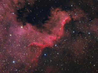
filter wheel (right) Image Galleries
Example images captured with G2 cameras.
 |
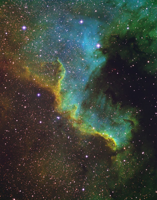
| Object |
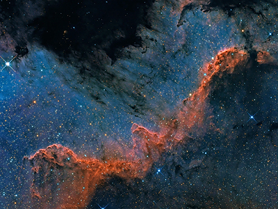
NGC7000 “North America” nebula |
| Author |
Thomas Lelu |
| Camera |
G2-4000 |
| Filters |
Hα, OIII, SII |
| Exposure |
23 hours |
| Telescope |
ASA 10” corrected Newtonian |
|
 |
| Object |
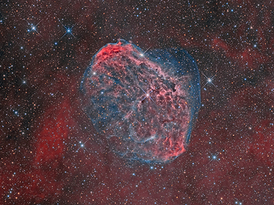
NGC6888 “Crescent” nebula |
| Author |
Thomas Lelu |
| Camera |
G2-4000 |
| Filters |
Hα, OIII |
| Exposure |
22 hours |
| Telescope |
ASA 10” corrected Newtonian |
|
 |
| Object |
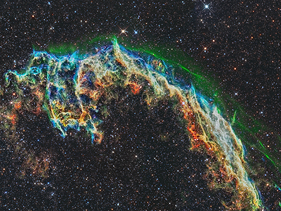
NGC6995 “Veil” nebula |
| Author |
Thomas Lelu |
| Camera |
G2-4000 |
| Filters |
Hα, OIII, SII |
| Exposure |
80 hours (2 panels, 40 hours each) |
| Telescope |
ASA 10” corrected Newtonian |
|
 |
| Object |
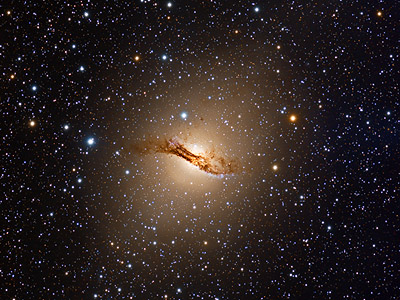
NGC5128 “Centaurus A” galaxy |
| Author |
Roger Gifkins |
| Camera |
G2-4000 |
| Filters |
RGB |
| Exposure |
28.8 hours |
| Telescope |
TOA 150 |
|
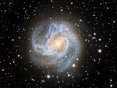 |
| Object |
M83 “Southern Pinwheel” galaxy |
| Author |
Roger Gifkins |
| Camera |
G2-4000 |
| Filters |
RGB |
| Exposure |
76.3 hours |
| Telescope |
TOA 150 |
|
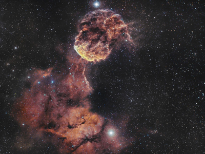 |
| Object |
IC443 “Jellyfish nebula” |
| Author |
Nicolas Kizilian |
| Camera |
G2-8300 |
| Filters |
Hα, OIII |
| Exposure |
8.5 hours |
| Telescope |
William Optics Zenithstar 66 |
|
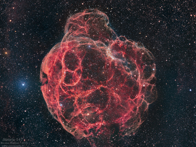 |
| Object |
Simeis 147 supernova remnant |
| Author |
Nicolas Kizilian |
| Camera |
G2-8300 |
| Filters |
Hα, OIII |
| Exposure |
42 hours |
| Telescope |
William Optics Zenithstar 66 |
|
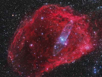 |
| Object |
NGC 6939, NGC 6946, Barnard 150, Sharpless 129,
Ou4, VdB 140 |
| Author |
Nicolas Kizilian |
| Camera |
G2-8300 |
| Filters |
RGB, narrow-band |
| Exposure |
47 hours |
| Telescope |
William Optics Zenithstar 66 |
|
 |
| Object |
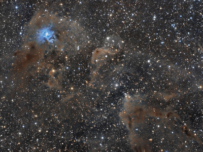
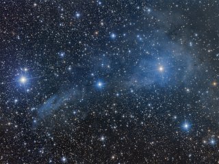
NGC7023 “Iris” nebula |
| Author |
Nicolas Kizilian |
| Camera |
G2-8300 |
| Filters |
Astrodon LRGB |
| Exposure |
6 hours |
| Telescope |
William Optics Zenithstar 66 |
|
 |
| Object |
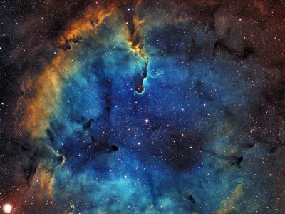
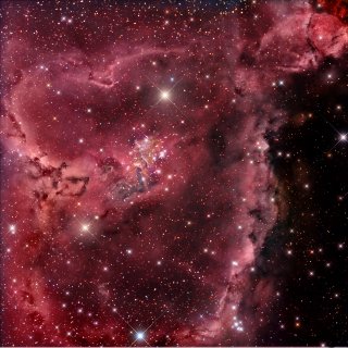
IC1396 “Elephant trunk” nebula |
| Author |
Nicolas Kizilian |
| Camera |
G2-8300 |
| Filters |
Hα, OIII |
| Exposure |
6 hours |
| Telescope |
William Optics Zenithstar 66 |
|
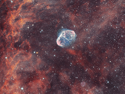 |
| Object |
NGC6888 “Crescent” nebula and “Soap
bubble” nebula |
| Author |
Nicolas Kizilian |
| Camera |
G2-8300 |
| Filters |
Hα, OIII |
| Exposure |
9 hours |
| Telescope |
William Optics Zenithstar 66 |
|
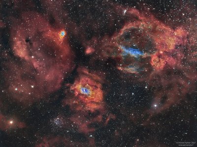 |
| Object |
NGC7635 “Bubble” nebula and
surroundings |
| Author |
Nicolas Kizilian |
| Camera |
G2-8300 |
| Filters |
Astrodon Hα,OIII |
| Exposure |
10.5 hours |
| Telescope |
William Optics Zenithstar 66 |
|
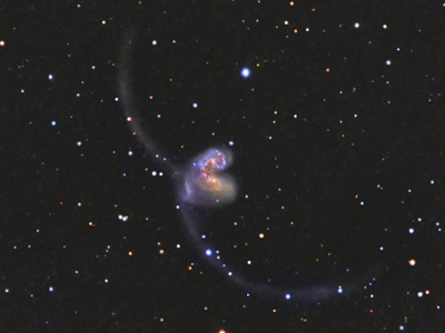 |
| Object |
NGC 4038 “Antennae” |
| Author |
Marco Burali |
| Camera |
G2-4000 |
| Filters |
LRGB |
| Exposure |
3 hours |
| Telescope |
TOA 150, f/5.8 |
|
 |
| Object |
NGC4725, NGC4712, NGC4747 |
| Author |
Marco Burali |
| Camera |
G2-4000 |
| Filters |
LRGB |
| Exposure |
5 hours |
| Telescope |
TSA 120, f/5.8 |
|
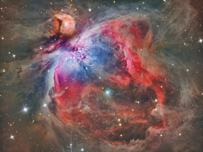 |
| Object |
M42 “Great Orion Nebula” |
| Author |
Reinhold Wittich |
| Camera |
G2-8300 |
| Filters |
LRGB, Hα, OIII and
SII |
| Exposure |
more than 10 hours |
| Telescope |
300 mm
Newtonian |
|
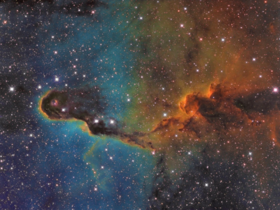 |
| Object |
“Elephant Trunk” nebula, part of
nebulosity complex IC1396 in Cepheus |
| Author |
Martin Myslivec |
| Camera |
G2-8300 |
| Filters |
Hα, OIII and SII |
| Exposure |
28 hours |
| Telescope |
300 mm
f/4.5 astrograph |
|
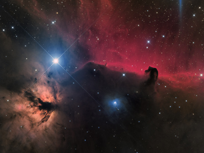 |
| Object |
“Flame” and “Horse Head” nebulae in
Orion |
| Author |
Jan Camek |
| Camera |
G2-8300 |
| Filters |
Astrodon Ha, Baader LRGB |
| Exposure |
7.2 hours |
| Telescope |
300 mm
f/2.9 astrograph |
|
 |
| Object |
IC1805 nebula complex |
| Author |
Jan Camek |
| Camera |
G2-8300 |
| Filters |
Astrodon Ha+OIII (bi-color) |
| Exposure |
14 hours |
| Telescope |
300 mm
f/2.9 astrograph |
|
 |
| Object |
M33 “Triangulum galaxy” |
| Author |
Jan Camek |
| Camera |
G2-8300 |
| Filters |
Astrodon Ha+OIII, Baader LRGB, IDAS LPS2 |
| Exposure |
12 hours |
| Telescope |
300 mm
f/2.9 astrograph |
|
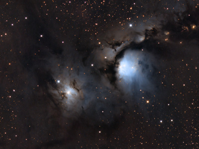 |
| Object |
M78 nebula |
| Author |
Jan Camek |
| Camera |
G2-8300 |
| Filters |
Baader LRGB |
| Exposure |
6.2 hours |
| Telescope |
300 mm
f/2.9 astrograph |
|
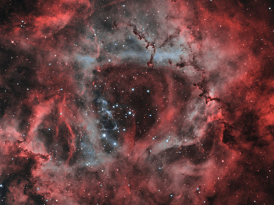 |
| Object |
NGC2244 “Rosette” nebula |
| Author |
Jan Camek |
| Camera |
G2-8300 |
| Filters |
Astrodon Ha 5nm, OIII 3nm (bi-color) |
| Exposure |
9 hours |
| Telescope |
300 mm
f/2.9 astrograph |
|
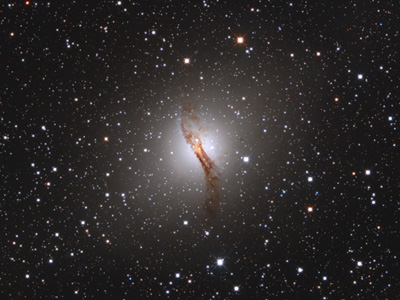 |
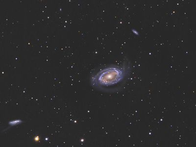
| Object |
NGC5128 “Centaurus A” galaxy |
| Author |
Jan Camek |
| Camera |
G2-8300 |
| Filters |
Baader LRGB |
| Exposure |
6.6 hours |
| Telescope |
300 mm
f/2.9 astrograph |
|
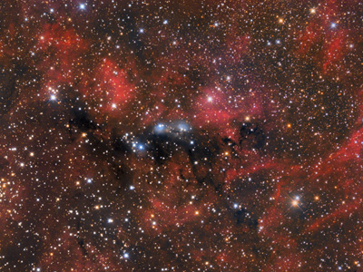 |
| Object |
NGC6914 nebula complex |
| Author |
Jan Camek |
| Camera |
G2-8300 |
| Filters |
Baader LRGB |
| Exposure |
6 hours |
| Telescope |
300 mm
f/2.9 astrograph |
|
 |
| Object |
WR134, nebulosity around a Wolf Rayet star in
Cygnus |
| Author |
Tommy Nawratil |
| Camera |
G2-8300 (LRGB + Hα +
OIII filters) |
| Telescope |
10 inch f/4
Newton |
|
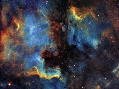 |
| Object |
NGC7000 “North America” a IC5070
“Pelican” |
| Author |
Ondrej Podlucky |
| Camera |
G2-8300 (+ narrow-band filters) |
| Exposure |
43 hours (mosaic of two
frames) |
| Telescope |
Borg 101ED + F4ED reducer |
|
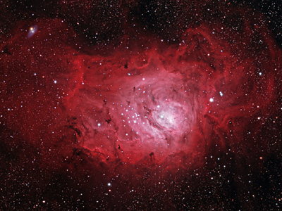 |
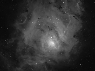
| Object |
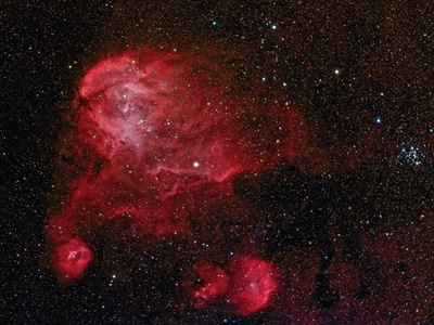
M8 “Lagoon” |
| Author |
David Kennedy |
| Camera |
G2-8300 (+ Ha, R, G, B filters) |
| Exposure |
9.5 hours |
| Telescope |
Borg 60ED |
|
 |
| Object |
IC1396 “Elephant's trunk” |
| Author |
Ondrej Podlucky |
| Camera |
G2-8300 (+ narrow-band filters) |
| Exposure |
27 hours |
| Telescope |
Borg 101ED + F4ED reducer |
|
 |
| Object |
Lambda Centauri region |
| Author |
David Kennedy |
| Camera |
G2-8300 (+ Ha, R, G, B filters) |
| Exposure |
8.9 hours |
| Telescope |
71fl miniBorg F/7.8 |
|
 |
| Object |
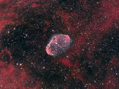
NGC6888 Crescent nebula |
| Author |
Jonas Fiedler |
| Camera |
G2-8300 (+ Ha, R, G, B filters) |
| Exposure |
4.5 hours |
| Telescope |
Takahashi FSQ 106 |
|
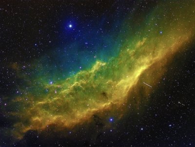 |
| Object |
NGC1499 California Nebula |
| Author |
Ondrej Podlucky |
| Camera |
G2-8300 (+ narrow-band filters) |
| Exposure |
28 hours |
| Telescope |
Borg 101ED + F4ED reducer |
|
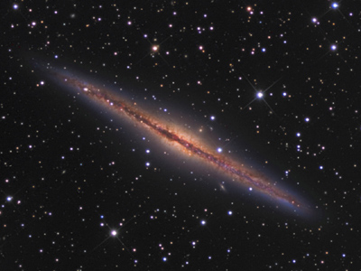 |
| Object |
NGC891 |
| Author |
Stefano Campani |
| Camera |
G2-8300 with Hα and RGB
filters |
| Exposure |
6.4 hours |
| Telescope |
24" (610 mm) RNT
Newton |
|
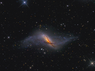 |
| Object |
NGC660 |
| Author |
Stefano Campani |
| Camera |
G2-8300 with Hα and RGB
filters |
| Exposure |
10.6 hours |
| Telescope |
24" (610 mm) RNT
Newton |
|
 |
| Object |
IC348 |
| Author |
Miloš Hroch |
| Camera |
G2-8300 |
| Telescope |
200 mm, f/2.9
astrograph (f/4 mirror + 0.73×
ASA corrector) |
|
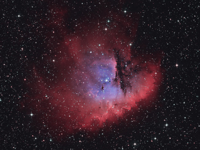 |
| Object |
NGC281 “Pacman nebula” |
| Author |
Miloš Hroch |
| Camera |
G2-8300 |
| Telescope |
200 mm, f/2.9
astrograph (f/4 mirror + 0.73×
ASA corrector) |
|
 |
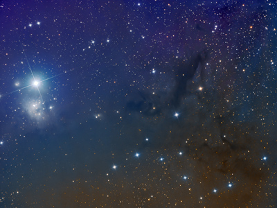
| Object |
VdB14, VdB15 |
| Author |
Miloš Hroch |
| Camera |
G2-8300 |
| Telescope |
200 mm, f/2.9
astrograph (f/4 mirror + 0.73×
ASA corrector) |
|
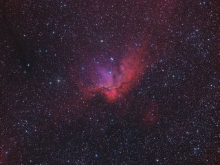 |
| Object |
NGC7380 “Wizard nebula” |
| Author |
Miloš Hroch |
| Camera |
G2-8300 |
| Telescope |
200 mm, f/2.9
astrograph (f/4 mirror + 0.73×
ASA corrector) |
|
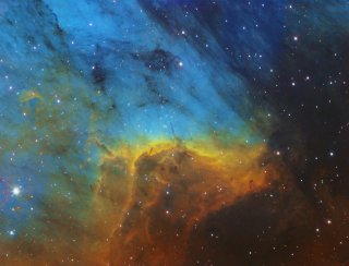 |
| Object |
IC5070 “Pelican Nebula” |
| Author |
Thomas Jäger |
| Camera |
G2-8300 |
| Telescope |
12" (305 mm) f/3.8
astrograph |
|
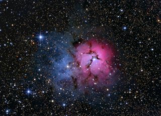 |
| Object |
M20 “Trifid” |
| Author |
David Kennedy |
| Camera |
G2-8300 |
| Telescope |
Vixen VC200L with reducer |
|
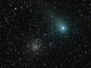 |
| Object |
Comet C2009 P1 Garradd and M71 |
| Author |
Martin Myslivec |
| Camera |
G2-8300 |
| Telescope |
185mm f/3.9 astrograph |
|
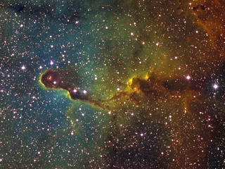 |
| Object |
IC1396 “Elephant Trunk” |
| Author |
Martin Myslivec |
| Camera |
G2-8300 (+narrow-band filters) |
| Telescope |
185mm f/3.9 astrograph |
|
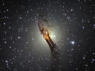 |
| Object |
NGC5128 “Centaurus A” |
| Author |
David Kennedy |
| Camera |
G2-8300 |
| Telescope |
Vixen VC200L with reducer |
|
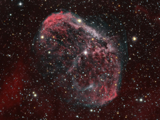 |
| Object |
NGC6888 “Crescent Nebula” |
| Author |
Patrick Hochleitner and Dieter Beer |
| Camera |
G2-8300 |
| Telescope |
Skywatcher BD 120ED + 0,85 flattener |
|
 |
| Object |
M101 |
| Author |
Christoph Gerhard |
| Camera |
G2-8300 |
| Telescope |
7-inch Maksutov |
|
 |
| Object |
NGC6559 |
| Author |
Resa Ghanawistschi |
| Camera |
G2-8300 |
| Telescope |
Pentax 75SDHF |
|
 |
| Object |
NGC7000 “North America” |
| Author |
Martin Myslivec |
| Camera |
G2-8300 (+ narrow-band filters) |
| Telescope |
185mm f/3.9 astrograph |
|
 |
| Object |
M101 |
| Author |
Manferd Fischer |
| Camera |
G2-8300 |
| Telescope |
ASA N8 |
|
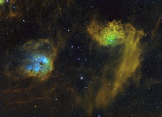 |
| Object |
IC405, IC410 |
| Author |
Ondrej Podlucky |
| Camera |
G2-8300 (+ narrow-band filters) |
| Telescope |
Borg 101ED + F4ED reducer |
|
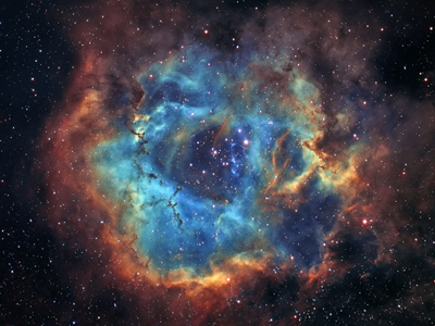 |
| Object |
NGC2237 “Rosette” |
| Author |
Ondrej Podlucky |
| Camera |
G2-8300 (+ narrow-band filters) |
| Telescope |
Borg 101ED + F4ED reducer |
|
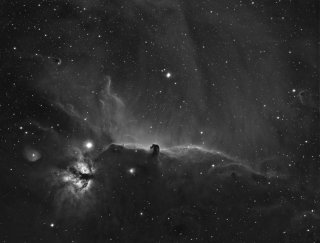 |
| Object |
IC434 “Horse Head” |
| Author |
Ondrej Podlucky |
| Camera |
G2-8300 (+ Hα) |
| Telescope |
Borg 101ED + F4ED reducer |
|
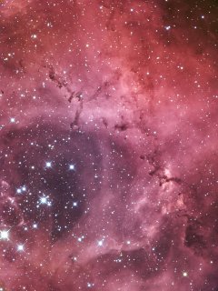 |
| Object |
NGC2237 “Rosette” |
| Author |
Tsutomu Chikazawa |
| Camera |
G2-8300 |
| Telescope |
Orion CT10 Newtonian |
|
 |
| Object |
M1 “Crab Nebula” |
| Author |
Tsutomu Chikazawa |
| Camera |
G2-8300 |
| Telescope |
Orion CT10 Newtonian |
|
 |
| Object |
M33 |
| Author |
Tsutomu Chikazawa |
| Camera |
G2-8300 |
| Telescope |
Orion CT10 Newtonian |
|
 |
| Object |
M51 “Whirlpool Galaxy” |
| Author |
Tsutomu Chikazawa |
| Camera |
G2-8300 |
| Telescope |
Orion CT10 Newtonian |
|
 |
| Object |
M81 “Boode Galaxy” |
| Author |
Tsutomu Chikazawa |
| Camera |
G2-8300 |
| Telescope |
Orion CT10 Newtonian |
|
 |
| Object |
NGC4725 |
| Author |
Martin Myslivec |
| Camera |
G2-8300 |
| Telescope |
185mm f/3.9 astrograph |
|
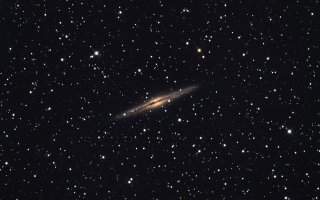 |
| Object |
NGC891 |
| Author |
Pavel Cagas |
| Camera |
G2-8300 |
| Telescope |
250mm f/5.4 Newton |
|
 |
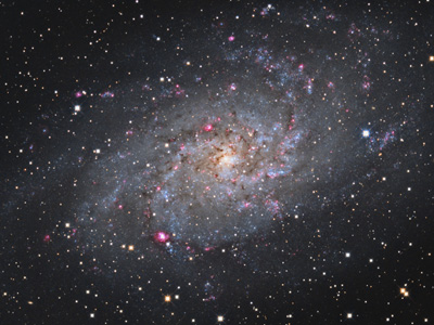
| Object |
M33 |
| Author |
Martin Myslivec |
| Camera |
G2-8300 |
| Telescope |
185mm f/3.9 astrograph |
|
 |
| Object |
NGC7000 “North America” |
| Author |
Martin Myslivec |
| Camera |
G2-8300 |
| Telescope |
185mm f/3.9 astrograph |
|
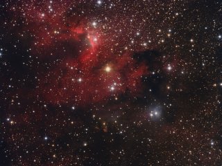 |
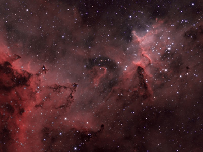
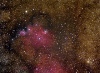
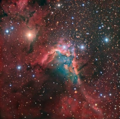
| Object |
“Cave Nebula” |
| Author |
Martin Myslivec |
| Camera |
G2-8300 |
| Telescope |
185mm f/3.9 astrograph |
|
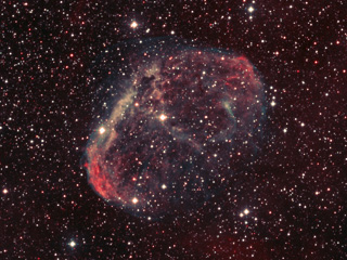 |
| Object |
NGC6888 “Crescent” (bi-color) |
| Author |
Martin Myslivec |
| Camera |
G2-8300 |
| Telescope |
185mm f/3.9 astrograph |
|
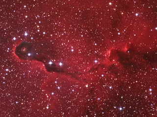 |
| Object |
IC1396 “Elephant Trunk” |
| Author |
Martin Myslivec |
| Camera |
G2-8300 |
| Telescope |
185mm f/3.9 astrograph |
|
 |
| Object |
“Omega Centauri” cluster |
| Author |
Robert Knox |
| Camera |
G2-8300 |
| Telescope |
110mm Borg ED |
|
 |
| Object |
M8 “Lagoon Nebula” |
| Author |
Robert Knox |
| Camera |
G2-8300 (+ Hα) |
| Telescope |
110mm Borg ED |
|
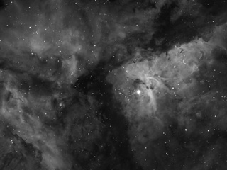 |
| Object |
Eta Cariane nebula |
| Author |
Robert Knox |
| Camera |
G2-8300 (+ Hα) |
| Telescope |
110mm Borg ED |
|
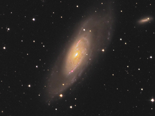 |
| Object |
M106 |
| Author |
Martin Myslivec |
| Camera |
G2-8300 |
| Telescope |
185mm f/3.9 astrograph |
|
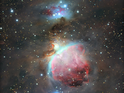 |
| Object |
M42 Orion Nebula |
| Author |
Samuele Gasparini |
| Camera |
G2-4000 |
| Telescope |
SkyWatcher 80ED + 0.85× flattener |
|
 |
| Object |
SH2 155 |
| Author |
Marco Burali |
| Camera |
G2-4000 (Hα + OIII +
RGB) |
| Telescope |
BRC 250 F5 |
|
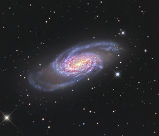 |
| Object |
NGC2903 |
| Author |
Marco Burali |
| Camera |
G2-4000 |
| Telescope |
Takahashi TOA 150 F7 |
|
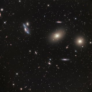 |
| Object |
Virgo Galaxy Cluster |
| Author |
Marco Burali |
| Camera |
G2-4000 |
| Telescope |
Takahashi TOA 150 F7 |
|
 |
| Object |
NGC7380 |
| Author |
Marco Burali |
| Camera |
G2-4000 |
| Telescope |
Takahashi TOA 150 F7 |
|
 |
| Object |
IC1805 |
| Author |
Marco Burali |
| Camera |
G2-4000 |
| Telescope |
Takahashi TOA 150 F7 |
|
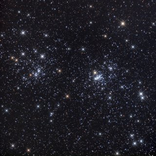 |
| Object |
NGC884 a NGC869 |
| Author |
Marco Burali |
| Camera |
G2-4000 |
| Telescope |
Takahashi TOA 150 F7 |
|
 |
| Object |
Gama Cygni |
| Author |
Marco Burali |
| Camera |
G2-4000 |
| Telescope |
Takahashi TOA 150 F7 |
|
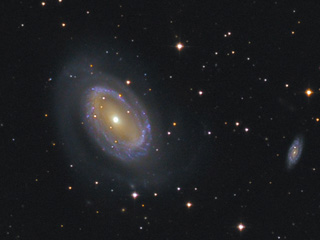
G2-0402, G2-1600 and G2-3200 Image Gallery
G2 CCD cameras with KAF detectors are primarily intended
for research work. They are only occasionally used for
“aesthetics astrophotography”. Following examples
represent both science observations and astrophotography
images.
Astronomy research
G2 cameras are appreciated by both professional
researchers and amateur astronomers involved in scientific
observations. Here are only a few examples, chosen from
huge amount of observations, be it extragalactic novae
discovery, minor planet photometry and astrometry,
variable star discovery and regular observations,
exoplanet transit observations etc.
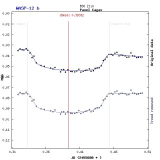 |
| Object |
WASP 12b exoplanet transit
observation |
| Author |
Pavel Cagas |
| Camera |
G2-3200 |
| Telescope |
250mm f/5.4 reflector |
|
Only 0.8mmag RMS difference from ideal light
cure 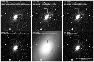 |
| Object |
Two new novae in M81 galaxy discovered
within three days |
| Author |
Pavel and Petr Cagas, Vaclav Pribik |
| Camera |
G2-3200 |
| Telescope |
265mm f/8 reflector |
|
This discovery is a record in the size of
telescope, used to discover nova in M81. The second
smallest has 750mm diameter. 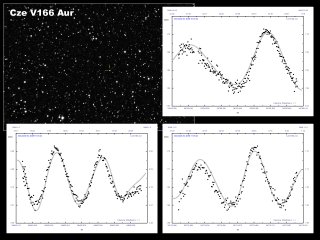 |
| Object |
New discovery of HADS (High Amplitude
Delta Scuti) variable star |
| Author |
Vaclav Pribik |
| Camera |
G2-1600 |
| Telescope |
254mm f/4.7 reflector |
|
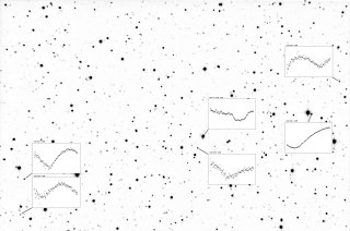 |
| Object |
5 new variable stars discovered during
HAT-P 20b exoplanet transit observations |
| Author |
Vaclav Pribik |
| Camera |
G2-1600 |
| Telescope |
254mm f/4.7 reflector |
|
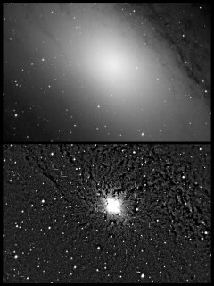 |
| Object |
9 novae in M31 galaxy |
| Author |
Kamil Hornoch |
| Camera |
G2-3200 |
| Telescope |
650mm f/3.6 reflector |
|
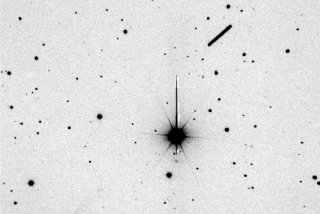 |
| Object |
Minor planet 2007/TU24 passing close to
Earth |
| Author |
Peter Kusnirak |
| Camera |
G2-3200 |
| Telescope |
650mm f/3.6 reflector |
|
Microscopy and material science
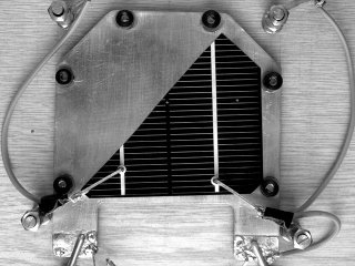 |
| Object |
Solar cell sample — visible light |
| Author |
Faculty of Electrical Engineering and
Communication, Brno University of Technology |
| Camera |
G2-3200 |
|
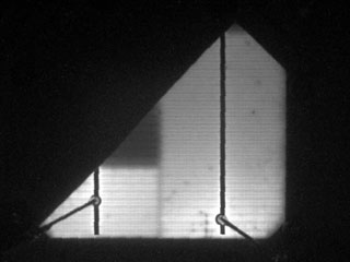 |
| Object |
Solar cell sample — near IR, conductive direction |
| Author |
Faculty of Electrical Engineering and
Communication, Brno University of Technology |
| Camera |
G2-3200 |
|
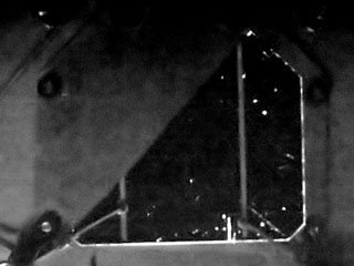 |
| Object |
Solar cell sample — near IR, micro-plasmas in barrier
direction |
| Author |
Faculty of Electrical Engineering and
Communication, Brno University of Technology |
| Camera |
G2-3200 |
|
Near-IR radiation of semiconductor (solar cell)
samples 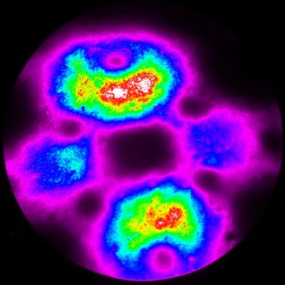 |
| Object |
Palladium layer on the tungsten sample
covered by tungsten oxide |
| Author |
J. Heyrovský Institute of Physical
Chemistry |
| Camera |
G2-0402 |
|
Field emission microscope images, camera field
of view is 800nm (1.5nm/pixel). Astrophotography
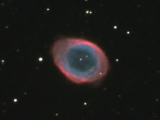 |
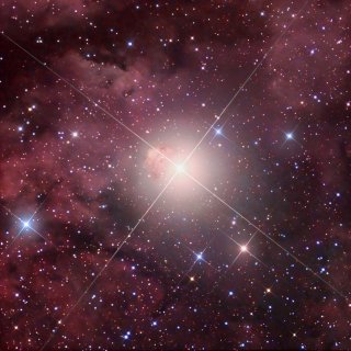
| Object |
M57 "Ring" nebula |
| Author |
Pavel Cagas |
| Camera |
G2-3200 |
| Telescope |
265mm f/8 Newtonian |
|
 |
| Object |
M27 "Dumbbell" nebula |
| Author |
Pavel Cagas |
| Camera |
G2-3200 |
| Telescope |
265mm f/8 Newtonian |
|
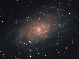
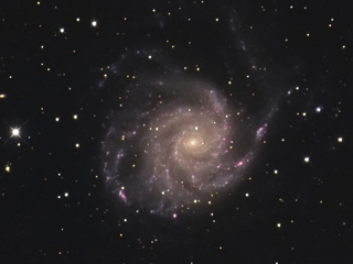 |
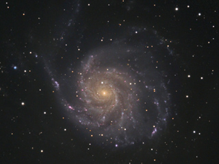
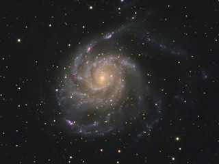
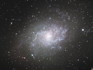
| Object |
M101 galaxy |
| Author |
Martin Myslivec |
| Camera |
G2-3200 |
| Telescope |
185mm f/3.9 astrograph |
|
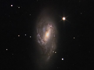 |
| Object |
M66 galaxy |
| Author |
Pavel Cagas |
| Camera |
G2-1600 |
| Telescope |
265mm f/8 Newtonian |
|
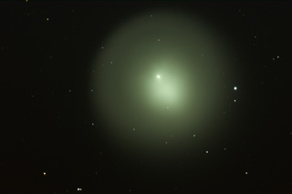 |
| Object |
Comet "Holmes" |
| Author |
Pavel Cagas |
| Camera |
G2-1600 |
| Telescope |
265mm f/8 Newtonian |
|
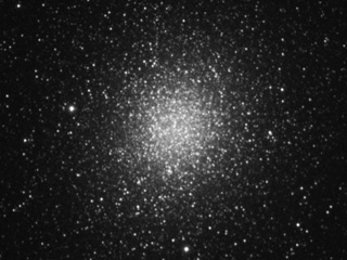
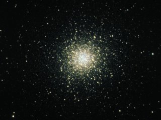 |
| Object |
Globular cluster M13 |
| Author |
Pavel and Petr Cagas |
| Camera |
G2-3200 |
| Telescope |
265mm f/8 Newtonian |
|
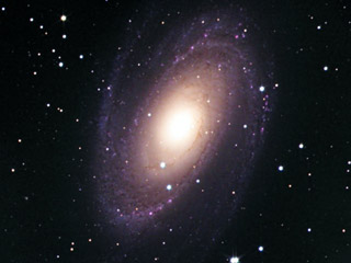 |
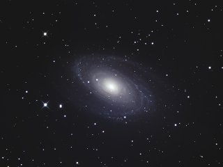
| Object |
M81 "Boode galaxy" |
| Author |
Pavel and Petr Cagas, Vaclav Pribik |
| Camera |
G2-3200 |
| Telescope |
265mm f/8 Newtonian |
|
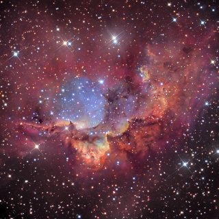
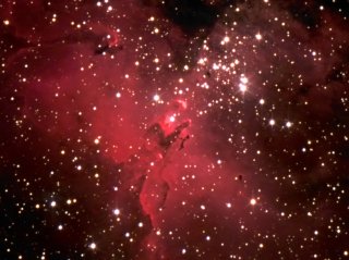 |
| Object |
M16 "Eagle nebula" |
| Author |
Pavel and Petr Cagas |
| Camera |
G2-3200 |
| Telescope |
265mm f/8 Newtonian |
|
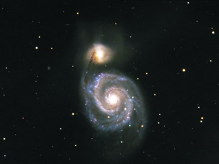 |
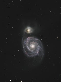
| Object |
M51 "Whirlpool galaxy" |
| Author |
Pavel and Petr Cagas |
| Camera |
G2-3200 |
| Telescope |
265mm f/8 Newtonian |
|
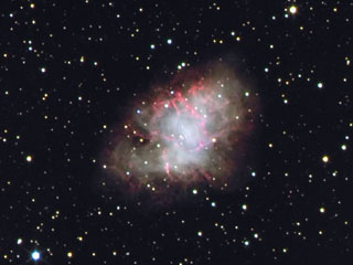 |
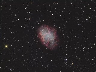
| Object |
M1 "Crab nebula" |
| Author |
Pavel Cagas |
| Camera |
G2-3200 |
| Telescope |
265mm f/8 Newtonian |
|
All images published with permission of their respective
authors.
|