|
Mechanical design of the C4 series of astronomical CMOS cameras
inherits from earlier CCD-based G4 Mark II cameras, which makes the C4
camera line fully compatible with vast range of telescope adapters,
off-axis guider adapters, filter wheels, Camera Ethernet adapters,
guiding cameras etc.
Rich software and driver support allow usage of C4 camera without
necessity to invest into any 3rd party software package thanks to
included free SIPS software package. However, ASCOM (for Windows) and
INDI (for Linux) drivers and Linux driver libraries are shipped with
the camera, provide the way to integrate C4 camera with broad variety
of camera control programs.
The C4 cameras are designed to work in cooperation with a
host Personal Computer (PC). As opposite to digital still cameras,
which are operated independently on the computer, the scientific
cooled cameras usually require computer for operation control, image
download, processing and storage etc. To operate the camera, you
need a computer which:
Is compatible with a PC standard and runs modern 32 or 64-bit
Windows operating system. Is an x86 or ARM based computer and runs 32 or 64-bit Linux
operating system. Support for x64 based Apple Macintosh computers is also
included.
C4 cameras are designed to be attached to host PC through very fast
USB 3.0 port. While C4 cameras remain compatible with older (and
slower) USB 2.0 interface, image download time is significantly
longer.
Alternatively, it is possible to use the Moravian Camera
Ethernet Adapter device. This device can connect up to four Cx
(and CCD based Gx) cameras of any type (not only C4, but also C1, C2
and C3) and offers 1 Gbps and 10/100 Mbps Ethernet interface for
direct connection to the host PC. Because the PC then uses TCP/IP
protocol to communicate with the cameras, it is possible to insert
WiFi adapter or other networking device to the communication path.
Hint: Please note that the USB standard allows usage of cable no
longer than approx. 5 meters and USB 3.0 cables are even shorter to
achieve very fast transfer speeds. On the other side, the TCP/IP
communication protocol used to connect the camera over the Ethernet
adapter is routable, so the distance between camera setup and the host
PC is virtually unlimited. Download speed is naturally significantly slower when camera is
attached over Ethernet adapter, especially when compared with direct
USB 3 connection.
The C4 cameras need an external power supply to operate. It is not
possible to run the camera from the power lines provided by the USB
cable, which is common for simple imagers. C4 cameras integrate highly
efficient CMOS sensor cooling, shutter and possibly filter wheel, so
their power requirements significantly exceed USB line power
capabilities. On the other side separate power source eliminates
problems with voltage drop on long USB cables or with drawing of
laptop batteries etc.
Also note the camera must be connected to some optical system (e.g.
the telescope) to capture images. The camera is designed for long
exposures, necessary to acquire the light from faint objects. If you
plan to use the camera with the telescope, make sure the whole
telescope/mount setup is capable to track the target object smoothly
during long exposures.
C4 Camera Overview
C4 camera head is designed to be easily used with a set of
accessories to fulfill various observing needs.
, with M size External filter wheel (middle) and with L size External filter wheel (right)")
C4 Camera without filter wheel (left), with “M”
size External filter wheel (middle) and with “L” size
External filter wheel (right) As opposed to smaller C2 and C3 camera models, which offer an
option to integrate filter wheel into camera shell, large C4
camera sensors need square 50×50 mm filters, too big to fit into
Internal filter wheel. So, using of External filter wheel is the
only option for C4 cameras.
There are two sizes of the External filter wheels
available:
Components of C4 Camera system include:
C4 camera head with standard cooling C4 camera head with Enhanced Cooling (EC)
option External Filter Wheel “M” size (5
positions) External Filter Wheel “L” size (7
positions) C1 guider camera Nikon bayonet adapter for Nikon compatible
lenses Canon EOS bayonet adapter for Canon compatible
lenses Off-Axis Guider with M68 × 1
thread adapter 1.75” dovetail rail for C4 camera head Camera Ethernet Adapter (x86 CPU) Camera Ethernet Adapter (ARM CPU) 5-positions “M” size filter wheel for 50 × 50 mm square filters 7-positions “L” size filter wheel for 50 × 50 mm square filters
CMOS Sensor and Camera Electronics
C4 cameras are equipped with Gpixel GSENSE4040 CMOS detectors
with resolution 4096 × 4096 pixels.
Pixel size is 9 × 9 μm, which
leads to almost 37 × 37 mm light
sensitive area.
The GSENSE4040 sensor is available in two
versions:
The later one shows exceptional quantum efficiency as the
sensor armature is hidden behind the silicon chip and 100% of the
pixel area faces the incoming light. Also, the sensor read noise
is lower compared to the front illuminated version. Naturally the
back illuminated version of the sensor is significantly more
expensive, which is reflected in the higher C4 BSI camera
price.
The GSENSE4040 sensor is equipped with 12-bit ADCs (Analog to
Digital Converters) only. However, there are two sets of ADCs
inside the sensor, each capable to digitize the image with
different gain — one set of ADCs uses
low-gain channel, while the second set uses high-gain channel.
Both 12-bit outputs of each ADC set can be combined to single
image with true 16-bit dynamic range (such combined image is often
called 16-bit HDR for High Dynamic Range).
Camera Electronics
CMOS camera electronics primary role, beside the sensor
initialization and some auxiliary functions, is to transfer
data from the CMOS detector to the host PC for storage and
processing. So, as opposite to CCD cameras, CMOS camera design
cannot influence number of important camera features, like the
dynamic range (bit-depth of the digitized pixels).
Sensor linearity
The sensors used in C4 cameras show very good linearity in
response to light. This means the camera can be used for
advanced research projects, like the photometry of variable
stars and transiting exoplanets etc.
Response of GSENSE4040 sensor in 12-bit low-gain
mode (left) and in 12-bit high-gain mode (right) Combination of both low-gain and high-gain digitization
channels into single 16-bit HDR image is designed to carefully
preserve linear response to light. What's more, resulting
16-bit image does not combine full dynamic range of both
low-gain and high-gain channels, but takes only the perfectly
linear portions of both channels. So, the linearity of the
resulting 16-bit image is perfect within the full dynamic
range.

Response of GSENSE4040 sensor in 16-bit HDR
mode Download speed
C4 camera is equipped with on-board RAM, capable to hold
multiple full-resolution frames. Downloading of the image to
the host computer thus does not influence image digitization
process, as the download only transfers already digitized
images from camera memory.
Time needed to download single frame depends on the read
mode and also whether fast USB3 or slower USB2 is used:
| Read Mode |
12-bit low/high gain |
16-bit HDR |
| USB 3.0 |
0.125 s |
0.250 s |
| USB 2.0 |
0.797 s |
1.578 s |
Conversion factors and read noise
C4 cameras do not offer the users to set gain, beside the
two fixed low-gain and high-gain channels. 16-bit HDR image
covers whole sensor dynamic range and manipulating with gain
would bring no additional benefits.
There are significant differences in the sensor
characteristics between the FSI and BSI versions.
FSI version
| Read mode |
12-bit high-gain |
12-bit low-gain |
16-bit HDR |
| Full well capacity |
3,540 e- |
80,000 e- |
56,600 e- |
| Conversion factor |
0.85 e-/ADU |
19.5 e-/ADU |
0.85 e-/ADU |
| Read noise |
3.9 e- RMS |
34.5 e- RMS |
3.9 e- RMS |
BSI version
| Read mode |
12-bit high-gain |
12-bit low-gain |
16-bit HDR |
| Full well capacity |
1,500 e- |
43,600 e- |
30,260 e- |
| Conversion factor |
0.37 e-/ADU |
10.6 e-/ADU |
0.37 e-/ADU |
| Read noise |
2.4 e- RMS |
11.6 e- RMS |
2.4 e- RMS |
Exposure control
C4 cameras are capable of very short exposures, the
shortest exposure time is 20.64 μs.
However, the sensor employs so-called “rolling
shutter”. This means the exposure does not start over the
whole sensor at once, but exposure of subsequent lines begins
with approx. 21 μs delay and the whole
sensor is illuminated 84.54 ms after exposure
starts. Similarly, end of exposure and pixel digitization is
performed line by line with the same delay between lines.
There is no practical limit on maximal exposure length, but
in reality, the longest exposures are limited by saturation of
the sensor either by incoming light or by dark current (see
the following chapter about sensor cooling).
Hardware binning
The GSENSE4040 FSI sensor implements 2 × 2 binning mode in hardware in addition to
normal 1 × 1 binning.
However, the back-side illuminated version of this sensor
GSENSE4040BSI does not implement any binning mode in hardware.
Also, the camera driver and user’s applications offer much
wider variety of binning modes up to 3 × 3 and 4 × 4
pixels as well as all combinations of asymmetrical binning
modes 1 × 2, 1 × 3, 2 × 4
etc. This is why the camera driver performs all binning
combinations in software and does not rely on the limited
capabilities of the sensor hardware binning.
The negative side of software binning is the same download
time like the full-resolution 1 × 1 binned image download. For typical
astronomy usage the small fraction of second download time is
irrelevant, but for applications very sensitive to download
time, the driver offers usage of the hardware 2 × 2 binning. This mode can be turned on and
off using the parameter in the ‘cXusb.ini’ configuration file,
located in the same directory like the ‘cXusb.dll’ driver DLL
file itself.
[driver]
HWBinning = true
When the HWBinning parameter is set to
true, GSENSE4040 hardware binning is used. This
mode brings faster download time, but brings several
restrictions:
Maximal binning is limited to 2 × 2, higher binning modes are rem\not
available. Asymmetrical binning modes (1 × 2, 2 × 1)
are not allowed.
Warning: Hardware binning is supported by camera firmware
version 6.6 and later. The Windows SDK supports the hardware
binning from version 4.9 and the SIPS software package from
version 4.0. Sensor specifications and overscan area
The C4-16000 FSI cameras are supplied with Grade 1
sensors.
The BSI variants are available in all three grades from 0
to 2 because of the steep price increase of better grade
sensors.
| Defect |
Grade 0 |
Grade 1 |
Grade 2 |
| Total defect pixels |
200 |
300 |
400 |
| Clusters (3-9) |
15 |
20 |
25 |
| Clusters (10-25) |
1 |
5 |
8 |
| Clusters (26-40) |
0 |
0 |
1 |
| Clusters (>40) |
0 |
0 |
0 |
| Defect row/column (total) |
0 |
5 |
10 |
| Adjacent defect row/column |
0 |
0 |
0 |
The light gathering area of the GSENSE4040 sensors is
divided into 4 quadrants, slightly differing in bias levels.
This division may remain visible as slightly different
background levels, especially when the overall scene
illumination is low. Such uneven background typically does not
harm scientific measurements, as the differences are well
beyond background noise. But aesthetic astro-photography can
be negatively influenced if these differences are not removed
during image processing.
 area.")
Bias frame of the GSENSE4040 sensor, showing 4
quadrants with slightly different levels. The dark stripe on
the right is the black-level (overscan) area. The GSENSE4040 sensor contains shielded pixels, returning
black-level signal (also known as overscan area) in addition
to normal illuminated pixels. There are 64 black-level pixels
in each of 4096 rows. The C4-16000 camera includes these
pixels into each image, so the resulting image width is
4096 + 64 = 4160 pixels. The 64 pixels wide stripe of
black-level pixels is also visible on the image above.
However, the camera driver by default removes the overscan
area and returns only illuminated area of 4096 × 4096 pixels to the user. This function is
controlled by a parameter ‘C4Overscan’ in the section
‘[driver]’ of the driver configuration file ‘cXusb.ini’,
located in the same directory like the ‘cXusb.dll’ driver DLL
file itself.
[driver]
C4Overscan = false
When the parameter value is modified to ‘true’, image
returned from camera will include the 64 pixels wide
black-level overscan area to the right of the image.
Cooling and power supply
Regulated thermoelectric cooling is capable to cool the CMOS
sensor up to 35 °C below ambient temperature. The Peltier hot side
is cooled by a fans. The sensor temperature is regulated with
±0.1 °C precision. Cooling and precision regulation ensure the
dark current does not ruin long exposures and allow proper image
calibration.
The camera head contains two temperature sensors — the first sensor measures directly the temperature
of the CMOS sensor. The second one measures the temperature inside
the camera shell.

Back side of the C4 camera head contains vents for two
fans, cooling Peltir hot side The cooling performance depends on the environmental conditions
and also on the power supply. If the power supply voltage drops
below 12 V, the maximum temperature drop is lower.
| CMOS chip cooling |
Thermoelectric (Peltier modules) |
| Maximal cooling ΔT |
~35 °C below ambient (Enhanced cooling) |
|
~30 °C below ambient (Standard cooling) |
| Regulated cooling ΔT |
33 °C below ambient (Enhanced cooling) |
|
28 °C below ambient (Standard cooling) |
| Regulation precision |
0.1 °C |
| Hot side cooling |
Air cooling (two fans) |
Chip cooling specifications 
C4-16000 camera reaching -35°C sensor temperature below
ambient temperature Overheating protection
The C4 cameras are equipped with an overheating protection
in their firmware. This protection is designed to prevent the
Peltier hot side to reach temperatures above ~50°C sensor
cooling is turned off to stop heat generation by the hot side
of the Peltier TEC modules.
Turning the overheating protection on results in a drop in
cooling power, a decrease in the internal temperature of the
camera and an increase in the temperature of the sensor.
However, when the camera cools its internals down below the
limit, cooling is turned on again. If the environment
temperature is still high, camera internal temperature rises
above the limit an overheating protection becomes active
again.
Power supply
The 12 V DC power supply enables camera operation
from arbitrary power source including batteries, wall adapters
etc. Universal 100-240 V
AC/50-60 Hz, 60 W “brick” adapter is supplied with
the camera. Although the camera power consumption does not
exceed 50 W, the 60 W power supply ensures noise-free
operation.
| Camera power supply |
12 V DC |
| Camera power consumption |
<8 W without cooling |
| |
47 W maximum cooling |
| Power plug |
5.5/2.5 mm, center
+ |
| Adapter input voltage |
100-240 V AC/50-60 Hz |
| Adapter output voltage |
12 V DC/5 A |
| Adapter maximum power |
60 W |
Power supply specification Warning: The power connector on the camera head uses
center-plus pin. Although all modern power supplies use this
configuration, always make sure the polarity is correct if
other than the supplied power source is used. 
12 V DC/5 A power supply adapter for the C4
camera Mechanical Specifications
Compact and robust camera head measures only 154 × 154 × 65 mm (approx.
6 × 6 × 2.6 inches) for
the model with standard cooling. Enhanced cooling increases camera
depth by 11 mm.
The head is CNC-machined from high-quality aluminum and black
anodized. The head itself contains USB-B (device) connector and
12 V DC
power plug, no other parts (CPU box, USB interface, etc.), except
a “brick” power supply, are necessary. Another connector
allows control of optional external filter wheel. Integrated
mechanical shutter allows streak-free image readout, as well as
automatic dark frame exposures, which are necessary for
unattended, robotic setups.
| Internal mechanical shutter |
Yes, blade shutter |
| Shortest exposure time |
21 μs (electronic shutter) |
| Longest exposure time |
Limited by chip saturation only |
| Head dimensions |
154 mm × 154 mm × 65 mm
(standard cooling) |
| |
154 mm × 154 mm × 76 mm
(enhanced cooling) |
| Back focal distance |
33.5 mm
(base of adjustable adapters) |
| Standard cooling head weight |
1.6 kg
(without filter wheel) |
| |
2.5 kg
(with “M” external filter wheel) |
| |
2.8 kg
(with “L” external filter wheel) |
| Enhanced cooling head weight |
1.8 kg
(without filter wheel) |
| |
2.7 kg
(with “M” external filter wheel) |
| |
3.0 kg
(with “L” external filter wheel) |
Mechanical specification Mechanical shutter
C4 cameras are equipped with mechanical shutter, which is
very important feature allowing unattended observations (fully
robotic or just remote setups). Without mechanical shutter, it
is not possible to automatically acquire dark frames,
necessary for proper image calibration etc.
Mechanical shutter in the C4 cameras is designed to be as
reliable as possible, number of open/close cycles is virtually
unlimited, because there are no surfaces rubbing against each
other. The price for high reliability is slow shutter motion.
Luckily, mechanical shuttering is not necessary for exposure
control, only for taking dark frames and possibly bias
frames — all used CMOS sensors are
equipped with electronic shuttering.
Camera firmware optimizes the shutter operation to avoid
unnecessary movements. If a series of light images is taken
immediately one after another, the shutter remains open not to
introduce quite significant delay of the close/open cycle
between each pair of subsequent light images. In the case next
image has to be dark or bias frame, shutter closes prior to
dark frame exposure and vice versa — shutter remains closed if a series of dark
frames is acquired and opens only prior to next light frame.
If no exposure is taken for approximately 1 second while the
shutter is open (this means after a light image exposure),
camera firmware closes the shutter to cover the sensor from
incoming light.
Camera without filter wheel
C4 camera head front view dimensions, head with
thin adapter base side view dimensions C4 camera head with thick adapter base side view
dimensions Enhanced cooling variant

C4 camera head with Enhanced cooling side view
dimensions Camera with “L” External filter wheel

C4 camera head with External filter wheel front
view dimensions C4 camera head with External filter wheel side view
dimensions The “M” sized External Filter Wheel diameter is
smaller (see External Filter Wheel User's Guide), but the back
focal distance of all external filter wheels is identical.
Enhanced cooling with External filter wheel
variant

Enhanced cooling C4 camera head with External
filter wheel side view dimensions Back Focal Distance
The stated back focal distances (BFD) include corrections for
all optical elements in the light path (cold chamber optical
window, sensor cover glass, ...), fixed in the camera body. So,
stated values are not mechanical, but optical back focal
distances. However, no corrections for filters are included, as
the thicknesses of various filters are very different.
There are two groups of the telescope and lens
adapters, differing in back focal distance definition:
Adapters without strictly defined BFD. These
adapters are designed to provide as low BFD as
possible. Adapter with defined BFD. These adapters are
typically intended for optical correctors (field flatteners,
coma correctors, ...) and also for photographic lenses. Keeping
the defined BFD is necessary to ensure proper functionality of
correctors or to be able to achieve focus with photographic
lenses.
There are two variants of the M68 × 1 adapter available. The
version 1 consists of two parts (the base and the M68 threaded
ring attached with 5 screws) and thus its total height is
greater.

C4 camera without filter wheel and with M68 × 1 v1 threaded adapter provides 35 mm BFD 
C4 camera with External filter wheel and M68 × 1 v1 threaded adapter offers
47.5 mm
BFD The newer M68 × 1
adapter version 2 is machined from one piece and its total height
is smaller, which results into shorter total BFD.

C4 camera without filter wheel and with M68 × 1 v2 threaded adapter provides just
28.5 mm
BFD 
C4 camera with External filter wheel and M68 × 1 v2 threaded adapter offers
41 mm
BFD The BFD of the C4-OAG is 61.5 mm.

BFD of the C4 camera with External filter wheel and OAG
adapter is 61.5 mm Please note when the OAG has to be used with a camera without
filter wheel, it is necessary to use a thick adapter base of the
same thickness like the External filter wheel to keep the distance
from OAG to sensor constant. Otherwise, the guiding camera cannot
reach focus.
Optional accessories
Various accessories are offered with C4 cameras to enhance
functionality and help camera integration into imaging setups.
External filter wheels
When there is no filter wheel inside the camera head, all
electronics and firmware, intended to control it, stays idle.
These components can be utilized to control external filter
wheel with only little changes. Also the camera front shell
can be manufactured thinner, the space for filter wheel is
superfluous.
, with M size (center) and L size (right) External filter wheels")
C4 Camera without filter wheel (left), with
“M” size (center) and “L” size (right)
External filter wheels Telescope adapters
Usage of many common types of telescope and lens
adapters are ruled out by very large sensor used in C4
cameras. The sensor diagonal dimension of C4 cameras is
52 mm, which is greater than
outer dimensions of many adapter kinds. Only the M68
threaded and Canon EOS bayonet adapters are large enough not
to cause vignetting, Nikon lenses can be used in some
special cases.
M68 × 1 — adapter
with M68 × 1 inner thread and
47.5 mm back
focal distance. Canon EOS bayonet — standard Canon EOS lens adapter (“L”
size), preserves 44 mm back
focal distance. Nikon bayonet — standard Nikon lens adapter (“L” size),
preserves 46.5 mm back focal distance.
All telescope/lens adapters of the C4 series of cameras can
be slightly tilted. This feature is introduced to compensate
for possible misalignments in perpendicularity of the
telescope optical axis and sensor plane.
Adjusting the telescope adapter tilt (left) and
removing the tiltable adapter (right) Adapters are attached either directly to the
External filter wheel front plate or to the adjustable
adapter base mounted on the camera head.
C4 adapters are not mounted directly on the camera
head. Instead a tilting adapter base, holding the circular
spring, is always used. If the External filter wheel is used, the adapted
base is not necessary, as the Mark II External filter wheel
front plate is already designed to hold the spring and it
also contains threads to fix respective adapters.

Mark II External filter wheels are already designed
for adjustable telescope adapters Off-Axis Guider adapter
C4 camera can be optionally equipped with Off-Axis Guider
Adapter. This adapter contains flat mirror, tilted by 45° to
the optical axis. This mirror reflects part of the incoming
light into guider camera port. The mirror is located far
enough from the optical axis not to block light coming to the
main camera sensor, so the optics must be capable to create
large enough field of view to illuminate the tilted
mirror.

Position of the OAG reflection mirror relative to
optical axis The C4-OAG offers the M68 × 1
thread on the telescope side. The back focal distance is
61.5 mm.
If the OAG is used on camera without filter wheel, thicker
adapter base must be used to keep the Back focal distance and
to allow the guiding camera to reach focus.
C4 OAG adapter (left), OAG on C4 camera with thick
adapter base (right) OAG guider port is compatible with C0 and C1 cameras. It is
necessary to replace the CS/1.25” adapter
with short, 10 mm variant.
Because C1 cameras follow CS-mount standard, (BFD
12.5 mm), any
camera following this standard with 10 mm long 1.25” adapter
should work properly with the C4-OAG.
Attaching camera head to telescope mount
C4 cameras are equipped with two “tripod”
0.250-20UNC threads on the top side of the camera head, as
well as four metric M4 threaded holes.
Location of the threaded holes on the top part of
the C4 camera head (left), 1.75" bar for standard telescope
mounts (right) These threaded holes can be used to attach 1.75 inch
“dovetail bar” (Vixen standard). It is then possible to
attach the camera head, e.g. equipped with photographic lens,
directly to various telescope mounts supporting this
standard.
Spare desiccant containers
The C4 cameras are supplied with silica-gel container,
intended to dry the sensor cold chamber. This container can be
unscrewed and desiccant inside can be dried in the oven (see
the camera User's Manual).

The whole desiccant container can be baked to dry
the silica-gel inside or its content can be poured out after
unscrewing the perforated internal cap and baked
separately Container shipped with the camera by default does not
exceed the camera head outline. It is equipped with a slot for
tool (a plastic tool is included with every camera, but e.g.
some coin can be used, too), allowing releasing and also
tightening of the container. Containers intended for enhanced
cooling cameras are prolonged as the camera thickness is
greater in the case of this variant.

Containers for standard and enhanced cooling
cameras also in variants allowing tool-less
manipulation It is possible to order spare container, which makes
desiccant replacement easier and faster. It is possible to dry
the spare container with silicagel and then only to replace it
on the camera. Spare container is supplied including the
air-tight cap.
Spare container can be supplied also in a variant that
allows manipulation without tools. But this container is
longer and exceeds camera outline. If the space behind the
camera is not critical, this container can make desiccant
exchange even easier.
 and variant for tool-less manipulation (right)")
Silicagel container with slot (left) and variant
for tool-less manipulation (right) Camera head color variants
Camera head is available in several color variants of the
center plate. Visit manufacturer's web pages for current
offering.

C4 camera color variants Moravian Camera Ethernet Adapter
The Moravian Camera Ethernet Adapter allows connection of
up to 4 Cx cameras of any type on the one side and 1 Gbps
Ethernet on the other side. This adapter allows access to
connected Cx cameras using routable TCP/IP protocol over
practically unlimited distance.
The Moravian Camera Ethernet Adapter device (left)
and adapter with two connected cameras (right) Moravian Camera Ethernet Adapter devices are described in
detail here.
Software support
Always use the latest versions of the system driver package for
both Windows and Linux system. Older versions of drivers may not
support new camera models or latest versions or existing
series.
If the camera is controlled through the Moravian Camera
Ethernet Adapter, make sure the device firmware is updated to
the latest version available.
Also, always use the latest version of the SIPS software
package, older versions may not support latest cameras correctly.
If a driver for 3rd party software package is used
(e.g. ASCOM or INDI drivers), always update the driver to the
latest available version.
SIPS
Powerful SIPS (Scientific Image Processing System)
software, supplied with the camera, allows complete camera
control (exposures, cooling, filter selection etc.). Also
automatic sequences of images with different filters,
different binning etc. are supported. With full ASCOM standard
support, SIPS can be also used to control other observatory
equipment. Specifically the telescope mounts, but also other
devices (focusers, dome or roof controllers, GPS receivers
etc.).
SIPS also supports automatic guiding, including image
dithering. Both “autoguider” port hardware interface
(6-wire cable) and mount “Pulse-Guide API” guiding
methods are supported. For hi-quality mounts, capable to track
without the necessity to guide at last during one exposure,
inter-image guiding using the main camera only is
available.
")
SIPS controlling whole observatory (shown in
optional dark skin) But SIPS is capable to do much more than just camera and
observatory control. Many tools for image calibration, 16 and
32 bit FITS file handling, image
set processing (e.g. median combine), image transformation,
image export etc. are available.
SIPS handles FITS files, supports image calibration
and processing As the first “S” in the abbreviation SIPS means
Scientific, the software supports astrometric image reduction
as well as photometric processing of image series.
SIPS focuses to advanced astrometric and
photometric image reduction, but also provides some very
basic astro-photography processing SIPS software package is freely available for download from this www site. All functions
are thoroughly described in the SIPS User's Manual, installed
with every copy of the software.
Automatic guiding
SIPS software package allows automatic guiding of the
astronomical telescope mounts using separate guiding
camera. Proper and reliable automatic guiding utilizing
the computational power of Personal Computer (e.g.
calculation of star centroid allows guiding with sub-pixel
precision) is not simple task. Guiding complexity
corresponds to number of parameters, which must be entered
(or automatically measured).

The SIPS “Guider” tool window The “Guiding” tool allows switching of
autoguiding on and off, starting of the automatic
calibration procedure and recalculation of autoguiding
parameters when the telescope changes declination without
the necessity of new calibration. Also swapping of the
German Equatorial mount no longer requires new autoguider
calibration. There is also a graph showing time history of
guide star offsets from reference position in both axes.
The length of graph history as well as the graph range can
be freely defined, so the graph can be adjusted according
to particular mount errors and periodic error period
length. Complete log of calibration procedure, detected
offsets, correction pulses etc. is also shown in this
tool. The log can by anytime saved to log file.
An alternative to classic autoguiding is the
inter-image guiding, designed for modern mounts, which are
precise enough to keep tracking with sub-pixel precision
through the single exposure, and irregularities only
appear on the multiple-exposure time-span. Inter-image
guiding then performs slight mount position fixes between
individual exposures of the main camera, which eliminates
“traveling” of the observed objects through the
detector area during observing session. This guiding
method uses main imaging camera, it does not use another
guiding camera and naturally does not need neither OAG nor
separate guiding telescope to feed the light into it.

Inter-image guiding controls in the
Guiding tab of the Imager Camera tool
window Drivers for 3rd party programs
Regularly updated Sofware Development Kit for Windows allows to
control all cameras from arbitrary applications, as well as
from Python scripts etc.
There are ASCOM standard drivers available together with
native drivers for some 3rd party programs (for
instance, TheSkyX, AstroArt, etc.). Visit the download page of this server to see a list of
all supported drivers.
Libraries and INDI standard drivers for 32-bit and 64-bit
Linux working on x86 and ARM processors are available as well. Also drivers for TheSkyX
running on macOS are supplied with all cameras.
Shipping and Packaging
C4 cameras are supplied in the foam-filled, hard
carrying case containing:
Camera body with a user-chosen telescope adapter. If
ordered, the filter wheel is already mounted inside the camera
head and filters are threaded into place (if ordered). A 100-240 V AC input, 12 V DC output
“brick” adapter with 1.8 m
long power cable. 2 m long USB 3.0 A-B cable
for connecting camera to host PC. USB Flash Drive with camera drivers, SIPS software
package with electronic documentation and PDF version of
User's Manual. A printed copy of camera User's Manual
C4 cameras are shipped in the foam-filled carrying case
(left), larger case is used if camera is ordered with external
filter wheel (right) Image Gallery
Example images captured with G4 cameras.
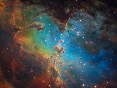 |
| Object |
M16 “Eagle” nebula |
| Author |
CielAustral Group |
| Camera |
C4-16000 + EFW-L-7 |
| Filters |
R, G, B, Hα, OIII,
SII |
| Telescope |
Planewave CDK610 |
| Exposure |
132 hours |
|
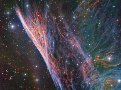 |
| Object |
NGC2736 |
| Author |
CielAustral Group |
| Camera |
C4-16000 + EFW-L-7 |
| Filters |
R, G, B, Hα, OIII,
SII |
| Telescope |
Planewave CDK610 |
| Exposure |
123 hours |
|
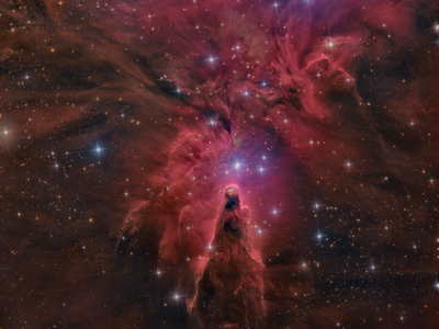 |
| Object |
NGC2264 “Cone” nebula |
| Author |
CielAustral Group |
| Camera |
C4-16000 + EFW-L-7 |
| Filters |
R, G, B, Hα, OIII,
SII |
| Telescope |
Planewave CDK610 |
| Exposure |
48.5 hours |
|
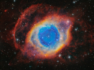 |
| Object |
NGC7293 “Helix” nebula |
| Author |
CielAustral Group |
| Camera |
C4-16000 + EFW-L-7 |
| Filters |
R, G, B, Hα, OIII,
SII |
| Telescope |
Planewave CDK610 |
| Exposure |
139 hours |
|
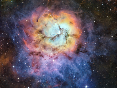 |
| Object |
M20 “Trifid” |
| Author |
CielAustral Group |
| Camera |
C4-16000 + EFW-L-7 |
| Filters |
narrow-band Hα, SII,
OIII |
| Telescope |
Planewave CDK610 |
| Exposure |
70.5 hours |
| 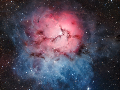 |
| Object |
M20 “Trifid” |
| Author |
CielAustral Group |
| Camera |
C4-16000 + EFW-L-7 |
| Filters |
RGB |
| Telescope |
Planewave CDK610 |
| Exposure |
10 hours |
|
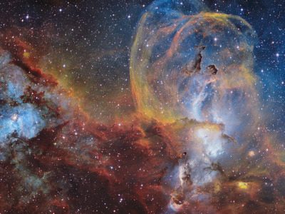 |
| Object |
NGC3586 |
| Author |
CielAustral Group |
| Camera |
C4-16000 + EFW-L-7 |
| Filters |
narrow-band Hα, SII,
OIII |
| Telescope |
Planewave CDK610 |
| Exposure |
70.5 hours |
| 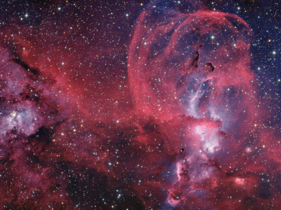 |
| Object |
NGC3586 |
| Author |
CielAustral Group |
| Camera |
C4-16000 + EFW-L-7 |
| Filters |
RGB |
| Telescope |
Planewave CDK610 |
| Exposure |
10 hours |
|
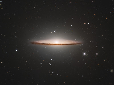 |
| Object |
M104 “Sombrero” galaxy |
| Author |
CielAustral Group |
| Camera |
C4-16000 + EFW-L-7 |
| Filters |
R, G, B, Hα, OIII |
| Telescope |
CDK 1000 (Chile) |
| Exposure |
16 hours |
|
Jmages published with permission of their respective
authors.
| 