|
The new CG series of auto-guiding and planetary cameras are
only the reshaped C0 series:
The new CG camers (left), compared to the C0 model
(right) CG camera models are equipped with Sony IMX global shutter
CMOS detectors with 3.45 × 3.45 μm square pixels. Individual models differ in resolution
and dynamic range.
| Model |
CMOS sensor |
Resolution |
Digitization |
Pixel size |
Image area |
| CG-1500 |
IMX273 |
1456 × 1088 pixels |
8-bit, 12-bit |
3.45 × 3.45 μm |
5.02 × 3.75 mm |
| CG-3000 |
IMX252 |
2064 × 1544 pixels |
8-bit, 12-bit |
3.45 × 3.45 μm |
7.12 × 5.33 mm |
| CG-3000A |
IMX265 |
2064 × 1544 pixels |
12-bit |
3.45 × 3.45 μm |
7.12 × 5.33 mm |
| CG-5000 |
IMX250 |
2464 × 2056 pixels |
28-bit, 12-bit |
3.45 × 3.45 μm |
8.50 × 7.09 mm |
| CG-5000A |
IMX264 |
2464 × 2056 pixels |
12-bit |
3.45 × 3.45 μm |
8.50 × 7.09 mm |
C2 camera with XS-sized filter wheel, C2-OAG, and CG
auto-guider C5 camera with XL-sized filter wheel, C5-OAG, and CG
auto-guider CG cameras were designed especially with automatic mount guiding on
mind. They work in connection with a host computer (PC). Guiding
corrections are not calculated in the camera itself, it only sends
acquired images to the PC. The software running on the PC calculates
the difference from required state and sends appropriate corrections
to the telescope mount. The plus side of using a host PC CPU to
process images is the fact, that current PCs provide overwhelming
computational power compared to any embedded processor inside the
guiding camera. Guiding algorithms then can determine star position
with sub-pixel precision, can match all stars detected within the
field of view to calculate average difference, which limits the
effects of seeing, etc.
Calculated corrections can be sent back to mount using PC-to-mount
link. If the mount controller does not support so-called “Pulse
Guide” commands, it is possible to use the “Autoguider”
port. It is enough to connect the CG camera and the mount using
standard 6-wire cable and guide the mount through the camera.

Standard 6-pin Autoguider Port is located beside the USB3
port on the back side of the CG cameras The Autoguider port follows the de-facto standard introduced by
SBIG ST-4 autoguider. The pins have the following functions:
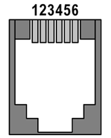 |
| 1 |
R.A. + (Right) |
| 2 |
Dec + (Up) |
| 3 |
Dec – (Down) |
| 4 |
R.A. – (Left) |
| 5 |
Common (Ground) |
| 6 |
Not connected |
|
| 