New hardware support
Support for new devices like Gx Cameras with Ethernet Interface
and implementation of ASCOM interfaces for cameras, filter wheels,
focusers, telescope mounts and observatory domes are the most
important enhancements of SIPS version 2.2.
Gx Camera Ethernet Interface
Gx Camera Ethernet Adapter allows connection of Gx series
cameras (models G0 to G4) to the control computer using
Ethernet interface and TCP/IP protocol stack (this means over
Local or Wide Area Networks). Single Gx Camera Ethernet
Adapter contains four USB 2.0 ports and allows connection
of up to four Gx cameras at the same time (regardless of the
specific series, cameras can be freely combined).
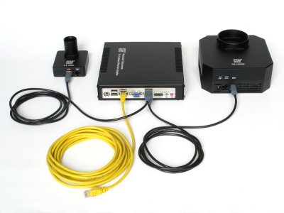
Gx Camera Ethernet Adapter with G4 and G1 cameras
connected Due to differences in G0/G1 and G2/G3/G4 camera features,
there are two different drivers for these series of cameras
connected through USB interface. But when these cameras are
connected over the TCP/IP, the Gx Camera Ethernet Adapter
firmware handles all the different features and there are no
significant differences for the control computer. This is why
a single driver for all Gx cameras with Ethernet
interface exists.
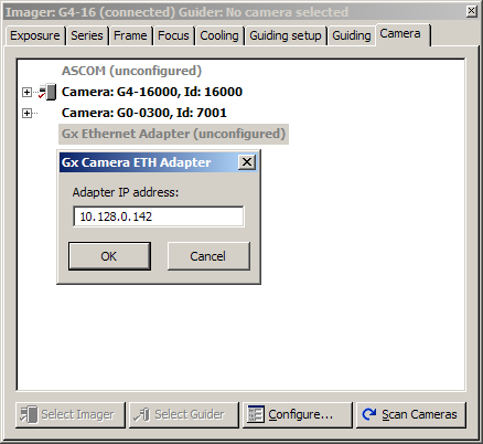
Setting of Gx Camera Ethernet Adapter IP
address The Gx Camera Ethernet Adapter hardware and configuration
is described in detail here.
ASCOM devices
ASCOM standard defines interfaces between control software
running on a PC and various hardware devices, used to run
astronomical observatories. This unified software layer thus
allows usage of various devices without the necessity to
implement native driver for every software package. The
benefits are obvious and important—development and support cost is significantly
reduced (it is enough to write single ASCOM driver instead of
many drivers with different proprietary interfaces for every
software package) and also reliability is higher (it is easier
to properly implement and debug one driver compared to many
drivers for single device, often maintained individually).
ASCOM standard covers many different devices. SIPS
v2.2 supports the following ones:
Cameras and Filter Wheels: SIPS handles both
cameras and filter wheels as single integrated devices,
which is why both ASCOM cameras and ASCOM filter wheels are
configured in the CCD Camera tool. Still, ASCOM
handles both cameras and filter wheels individually, which
is why configuring of ASCOM camera in SIPS opens a dialog
box, which allows setting up of both ASCOM camera and ASCOM
filter wheel. 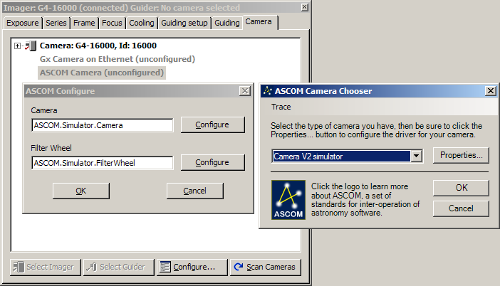
ASCOM Camera and ASCOM Filter Wheel
configuration
While SIPS supports connection of multiple cameras
at once, other devices can be connected only in one
instance. This is why available devices are offered only as
a drop-down list (combo box) with two buttons for
configuration and re-enumeration of all connected devices
 . .
Focusers: ASCOM focusers can be configured
in SIPS Focuser tool. 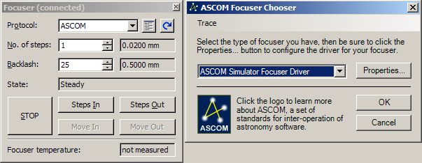
ASCOM Focuser configuration When a focuser is connected, other functions
in SIPS are available, like automatic focusing, refocus on
filter change (providing filter offsets are defined)
etc. Telescope mounts: ASCOM mount driver is
added to already existing Celestron NexStar and Meade LCX200
protocol drivers. 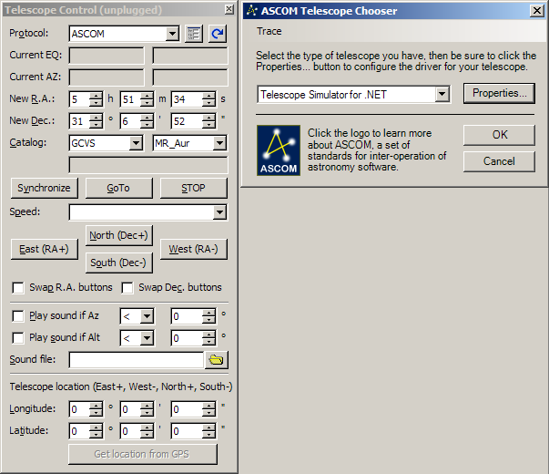
ASCOM Telescope mount Observatory dome: ASCOM Observatory dome
allows control of domes or roll-off roofs from the SIPS
environment. 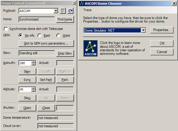
ASCOM Observatory dome
G1-1200
Support for new automatic guiding and planetary camera
G1-1200 with high quantum efficiency Sony ICX445 CCD detector
was added. G1-1200 guider is described here.
Driver configuration
SIPS uses the 'sips.ini' configuration file,
placed in the same directory like the 'sips.exe'
executable file, to load device drivers. If the driver has to
be used by SIPS, it must be defined in 'sips.ini'
file. This ini file was extended in version 2.2 to include all
new drivers.
[Camera]
g1ccd = g1ccd.dll
g2ccd = g2ccd2.dll
g3ccd = g3ccd.dll
Gx Camera on Ethernet = gxetha.dll
ASCOM Camera = ascom_camera.dll

[GPS]
Garmin USB = gps18.dll
NMEA = nmea.dll

[Telescope]
NexStar = nexstar.dll
LX200 = lx200.dll
ASCOM = ascom_tele.dll

[Focuser]
ASCOM = ascom_focuser.dll

[Dome]
ASCOM = ascom_dome.dll
It is possible to edit this file to contain only drivers
used by particular observing setup. Unused drivers can be
moved to arbitrary section name, which is skipped by SIPS. For
instance if only G2 and G1 USB cameras are used, this file can
be modified as follows:
[Camera]
g1ccd = g1ccd.dll
g3ccd = g3ccd.dll

[_Camera]
g2ccd = g2ccd2.dll
Gx Camera on Ethernet = gxetha.dll
ASCOM Camera = ascom_camera.dll

...
The [_Camera] section is not recognized by
SIPS, so all drivers in this sections are skipped (not loaded
and initialized).
When the Gx Camera Ethernet driver is configured (its IP
address is defined) and the device itself is not connected to
the network and/or not switched on, skipping its driver can
save approx. one second of startup time, for which the driver
waits for connection. Only after the attempt to connect to the
device fails on timeout, initiation sequence continues.
Hint: The 1 second connection timeout of the Gx Camera
Ethernet driver can be overridden in the
'gxetha.ini' configuration file. Parameter ConnectionTimeout
in the [driver] section defines the timeout (in
milliseconds), so it can be lowered if the device is on the
fast local area network or prolonged when the Gx Camera
Ethernet Adapter is truly remote and the connection requires
longer time. Let us note the Gx Camera Ethernet driver
parses both ConnectionTimeout and ConnectTimeout
keys to eliminate possible confusion when a different keyword
is used. New features
SIPS v2.2 was enhanced with several new features, beside the
new hardware support.
Adjusting to High-DPI displays
Using of high-resolution displays of relatively small
physical dimensions leads to shrinking of displayed GUI
elements to sizes hardly distinguishable and texts becomes
almost unreadable. Windows offers enlarging of “screen
density”, expressed as DPI (dots per inch), from default
96 DPI do higher values of
120 DPI (125%), 144 DPI (150%) or other user defined values.
The only effect of higher DPI is enlarging of the fonts used
on screen. Font size is defined in so-called points
(abbreviation “pt”), which is a device-independent
unit. E.g. 12 pt font should have
the same physical size regardless if printed on 300 DPI or 1200 DPI printer. It is up to the application to
update the size of GUI elements to take greater pixel size of
all texts into account .
SIPS v2.2 added adjusting of its GUI elements to higher DPI
screens (and larger fonts used).
SIPS CCD Camera tool window on standard
96 DPI screen (left) and on
150% 144 DPI screen
(right) Adding filter offset information
Because there is no way how to determine the actual filters
in the filter wheel automatically, the camera driver reads the
'g3ccd.ini' file to determine actual configuration
of filters, which will be then reported to the SIPS. The
'g3ccd.ini' file is placed in the same directory
where the actual driver files (especially the
'g3ccd.dll' library) are installed. This file is
ordinary text file following the .INI files conventions.
If multiple cameras handled by the same driver are used, it
is possible to include camera ID into the file name, e.g.
'g3ccd.2158.ini' will be used for camera ID=2158
only (note leading zeros are not allowed in the ID). Driver
searches for the ID-specific file name first and only if it is
not found, it tries to open generic ini file name.
Here is the example of the 'g3ccd.ini' file:
[filters]
Luminance, Gray, 660
Red, LRed, 660
Green, LGreen, 660
Blue, LBlue, 660
Clear, 0, 0
Filters are described in the [filters]
Section. Every line in this section describes one filter
position. Filter description is a comma-separated list of
three values:
Filter name: This name is returned to the
client application, which can use it to list available
filters in the filter wheel. Filter color: This color can be used by
client application to display the filter name with
a color, hinting the filter type. The color can be
expressed by a name (White, Red, LRed, etc.) or directly by
number representing the particular color (0 represents
black). Filter offset: Distance to move the focuser
to refocus upon filter change. Plan-parallel glass shifts
the actual focus position back for 1/3 of the glass
thickness (exact value depends on the glass refraction
index, but for almost all glasses 1/3 is very close to exact
value). Refocusing is useful when changing filters of
different thickness among exposures or when some exposures
are performed through filters and other without filters at
all.
Filter offsets can be defined in focuser dependent steps or
in micrometers (μm). If the micrometers
are used, it is necessary to inform driver by the MicrometerFilterOffsets
parameter in the [driver] section of the ini
file.
[driver]
MicrometerFilterOffsets = true

[filters]
Luminance, Gray, 660
...
Hint: Value of the MicrometerFilterOffsets
parameter can be expressed as true or false,
as well as 0 (for false) or 1 (for true). If micrometers are used and the particular focuser driver
provides information about the size of single step, SIPS is
the able to calculate necessary steps to move focuser to
refocus properly. Refocusing upon filter change can be
switched on in the CCD Camera tool (see the image
in the above section).
Other enhancements
Other enhancements touched various parts of the
SIPS:
Driver for G0 and G1 camera now offers binning up to
4 × 4 pixels. Hint: When
a camera without binning support is used as guider, SIPS
still offered binning and implements this function in
software. But G0/G1 camera used as main imager did not allow
binning and if binning was required, explicit software
binning had to be chosen in the New Images
Transform SIPS tool. CCD Camera tool offers the possibility to
refocus upon filter change, providing individual filter
offsets are defined and focuser driver is defined and
online. Autofocus feature of the CCD Camera tool
was enhanced to be more robust. When a GEM mount is used inside the dome, dome slot
is often too narrow to provide enough opening for the scope
regardless of the tube-to-pier orientation. So it is
necessary to shift the dome slot azimuth depending on the
telescope coordinates and OTA position to the pier (east or
west). SIPS v2.2 added exact analytical calculation of the
dome slot azimuth correction. Necessary parameters are
defined in the GEM and Dome Parameters dialog
box. 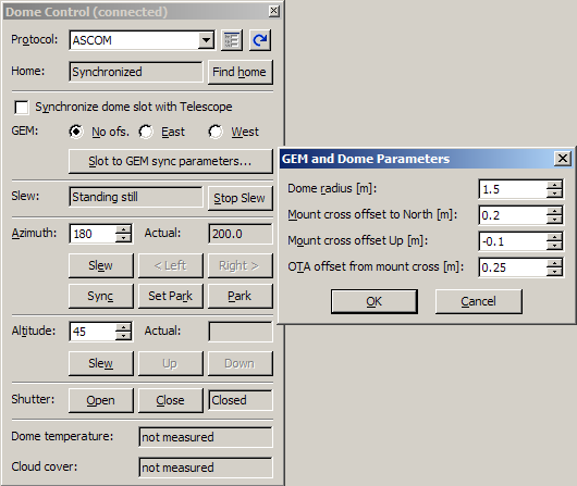
GEM mount and dome parameters
definition
Bug fixes
The following problems were fixed:
Definition of exposure series in the Series
tab of the CCD Camera tool required hitting the Enter
key after each parameter was defined, just clicking another cell
was not enough. New version fixes this problem. NexStar protocol requires switching off of the tracking
before GoTo command is issued (or generally any movement faster
then the lowest guiding speed). NexStar protocol driver sampled
the mount tracking only upon startup to correctly restore the
tracking after GoTo (tracking is North, South of Off). The
problem was when SIPS was launched and NexStar initiated before
the telescope was aligned, which means in time the mount
tracking was Off. Then any move resulted to restoring of the Off
tracking state. New driver version samples the Tracking before
each move command is issued.
SIPS v2.2 is a freeware and can be downloaded from the download section of this WWW site.
| 