|
The C0, CG, and C1 cameras share majority of features, like the
used sensors, USB interface, autoguider port, etc. At the first view,
the only difference is the size and shape of the camera body.

C0 camera The main differentiating feature of the CG series is the flattened
camera shape.

CG camera Greater dimensions of the C1 models allowed adding of some
features, not available on the C0 cameras, like cooling fan and
mounting threaded holes.

C1 camera Sometimes the C0 or C1 camera cannot be used on OAG because of its
shape. Both C0 and C1 cameras exceed the front plane, defined by the
OAG front thread, and thus they can possibly interfere with the
telescope's rear mounting interface. The CG cameras are designed not
to exceed the OAG in the front. But otherwise, the CG cameras are
essentially the C0 ones in the flat casing.
C5 camera with XL-sized filter wheel, C5-OAG, and CG
auto-guider
| Feature |
C0 |
CG |
C1 |
| Dimensions |
50 × 50 × 40.4 mm |
50 × 34 × 68 mm |
57 × 57 × 46.4 mm |
| Weight |
115 g |
138 g |
170 g |
| Cooling fan |
No |
No |
Yes |
| Tripod and metric threads |
No |
No |
Yes |
, CG (middle), and C1 (right) cameras")
Comparing the C0 (left), CG (middle), and C1 (right)
cameras C0, CG, and C1 camera models are equipped with Sony IMX global
shutter CMOS detectors with 3.45 × 3.45 μm square pixels.
Individual models differ in resolution only.
All used sensors utilize global electronic shutter. This means
every pixel within the image is exposed in the same time, as opposed
to rolling shutter sensors, which exposes individual lines one after
another. There is no difference for long exposures of static objects,
but imaging of moving objects using short exposure time using rolling
shutter leads to image shape distortions.
Two camera lines are available depending on the available
dynamic range (bit-depth of the digitized pixels):
Cameras with Sony IMX sensors supporting 8- and 12-bit
digitization. Because every 12-bit pixel occupies two bytes
when transferred to host PC, 12-bit image download time is longer
compared to 8-bit image. Maximal FPS in 8-bit mode is then
significantly higher. Cameras with Sony IMX sensors supporting 12-bit
digitization only. As the 12-bit read mode is always used for
long-exposure applications (astronomical photography, scientific
research) either way, lower theoretical download time in 8-bit mode
brings no limitations for real-world scenarios. All other parameters
being same (sensor size, resolution, pixels size, noise, …), lower
price of these cameras may be then very attractive.
Camera models with 8- and 12-bit digitization:
| Model |
CMOS sensor |
Resolution |
Pixel size |
Image area |
| C0/CG/C1-1500 |
IMX273 |
1456 × 1088 pixels |
3.45 × 3.45 μm |
5.02 × 3.75 mm |
| C0/CG/C1-3000 |
IMX252 |
2064 × 1544 pixels |
3.45 × 3.45 μm |
7.12 × 5.33 mm |
| C0/CG/C1-5000 |
IMX250 |
2464 × 2056 pixels |
3.45 × 3.45 μm |
8.50 × 7.09 mm |
| C0/C1-12000 |
IMX253 |
4112 × 3008 pixels |
3.45 × 3.45 μm |
14.19 × 10.38 mm |
Camera models with 12-bit digitization only:
| Model |
CMOS sensor |
Resolution |
Pixel size |
Image area |
| C0/CG/C1-3000A |
IMX265 |
2064 × 1544 pixels |
3.45 × 3.45 μm |
7.12 × 5.33 mm |
| C0/CG/C1-5000A |
IMX264 |
2464 × 2056 pixels |
3.45 × 3.45 μm |
8.50 × 7.09 mm |
| C0/C1-12000A |
IMX304 |
4112 × 3008 pixels |
3.45 × 3.45 μm |
14.19 × 10.38 mm |
The C0, CG, and C1 cameras are designed to work in
cooperation with a host Personal Computer (PC). As opposite to
digital still cameras, which are operated independently on the
computer, the scientific cameras usually require computer for
operation control, image download, processing and storage etc. To
operate the camera, you need a computer which:
Is compatible with a PC standard and runs modern 32 or 64-bit
Windows operating system. Is compatible with a PC standard and runs 32 or 64-bit Linux
operating system. Support for x64 based Apple Macintosh computers is also
included.
Cameras are designed to be connected with the host PC through
USB 3.0 interface, operating at 5 Gbps. Cameras are also compatible
with USB 2.0 port to communicate with a host PC.
Alternatively, it is possible to use the Moravian Camera
Ethernet Adapter device. This device can connect up to four Cx
(with CMOS sensors) or Gx (with CCD sensors) cameras of any type and
offers 1 Gbps and 10/100 Mbps Ethernet interface for direct connection
to the host PC. Because the PC then uses TCP/IP protocol to
communicate with the cameras, it is possible to insert WiFi adapter or
other networking device to the communication path.
Hint: Please note that the USB standard allows usage of cable no
longer than approx. 5 meters and USB 3.0 cables are even shorter to
achieve very fast transfer speeds. On the other side, the TCP/IP
communication protocol used to connect the camera over the Ethernet
adapter is routable, so the distance between camera setup and the host
PC is virtually unlimited. The C0, CG, and C1 cameras do not need an external power supply to
operate, they are powered through the USB connection from the host
PC.
Note the camera must be connected to some optical system (e.g. the
telescope) to capture images. The camera is capable of long exposures,
necessary to acquire the light from faint objects. If you plan to use
the camera with the telescope, make sure the whole telescope/mount
setup is capable to track the target object smoothly during long
exposures.
C0, CG, and C1 Camera System
Components of the C0 and C1 Camera system
include:
C0 camera head with CS-mount adapter C1 camera head with CS-mount adapter C0 camera head with combined T-thread (M42×0.75) and
CS-mount adapter C1 camera head with combined T-thread (M42×0.75) and
CS-mount adapter C/CS-mount to 1.25” barrel adapter Short (10 mm) variant of
C/CS-mount to 1.25” barrel adapter, intended for usage with
OAG Off-Axis Guider adapter (OAG) for cooled C1+ and C2
cameras Extension tube with M48 × 0.75 thread and
55 mm back focal distance Extension tube with M42 × 0.75 thread and
55 mm back focal distance (standard
T-thread adapter) Adapter for Canon EOS bayonet lens Adapter for Nikon bayonet lens
C1 camera versions
The C1 cameras underwent several innovation cycles through its
lifetime. Versions 1 and 2 differ only internally and they are
indistinguishable from the user point of view. The 3rd
iteration of the C1 camera design allowed to make the camera head
7 mm thinner and 45 g lighter. Beside the smaller and lighter body,
all other features (used sensors, USB and autoguider interfaces,
download time, …) are the same.
 and v1/v2 (right) models shows the difference in camera thickness")
Comparison of the C1 v3 (left) and v1/v2 (right) models
shows the difference in camera thickness Camera Electronics
CMOS camera electronics primary role, beside the sensor
initialization and some auxiliary functions, is to transfer data
from the CMOS detector to the host PC for storage and processing.
So, as opposite to CCD cameras, CMOS camera design cannot
influence number of important camera features, like the dynamic
range (bit-depth of the digitized pixels).
Sensor linearity
The sensors used in C1 cameras shows very good linearity in
response to light. This means the camera can be used also for
entry-level research projects, like for instance photometry or
brighter variable stars etc.
 response to light")
C1-3000 (IMX252) response to light Download speed
As already noted, there are two lines of C0, CG,
and C1 camera series, differing in the used sensor. The
first series offers four different read modes:
8-bit slow mode with ~132 MPx/s digitization
speed 12-bit slow mode with ~72 MPx/s digitization
speed 8-bit fast mode with ~263 MPx/s digitization
speed 12-bit fast mode with ~132 MPx/s
digitization speed
The “A” version of C0, CG, and C1 cameras
offers only single read mode:
The digitization speeds mentioned above are valid for
USB 3.0 connection. Also please note the digitization speeds
do not necessarily lead to corresponding FPS, because every
image downloaded has to be processed and displayed, which also
consumes time. This time is negligible, if slow-scan camera
needs many seconds for image download, but in the case of fast
CMOS cameras, time for image processing in the PC (e.g.
calculation of image standard deviation etc.) can be longer
than image download itself.
Camera gain
Sensors used in C0, CG, and C1 cameras offer programmable
gain from 0 to 24 dB, which translates to the output signal
multiplication from 1× to
15.9×. Gain can
be set with 0.1 dB step.
Conversion factors and read noise
Generally, many sensor characteristics depend on the used
gain. Hence, we provide two lists of parameters for both
minimal and maximal gain.
| Digitization resolution |
12-bit |
12-bit |
8-bit |
8-bit |
| Sensor gain |
0 dB |
24 dB |
0 dB |
24 dB |
| Full well capacity |
11000 e- |
1100 e- |
2600 e- |
1100 e- |
| Conversion factor |
2.8 e-/ADU |
0.3 e-/ADU |
10.0 e-/ADU |
4.4 e-/ADU |
| Read noise |
2.2 e- RMS |
2.0 e- RMS |
4.2 e- RMS |
9.7 e- RMS |
Exposure control
C0, CG, and C1 cameras are capable of very short exposures.
The shortest exposure time is 125 μs
(1/8000 of second). This is also the step, by which the
exposure time is expressed. So, the second shortest exposure
is 250 μs etc.
Long exposure timing is controlled by the host PC and there
is no upper limit on exposure time. In reality the longest
exposures are limited by saturation of the sensor either by
incoming light or by dark current (see the following
sub-chapter).
Sensor Cooling
Dark current is an inherent feature of all silicone circuits.
It is called “dark”, because it is generated regardless if
the sensor is exposed to light or not. Dark current, injected into
individual pixels, appear in image as noise. The longer exposure,
the greater amount of noise is present in every image. As it is
generated by random movement of particles, it depends on the
temperature exponentially (this is why the noise generated by dark
current is also denoted “thermal noise”). Typically,
lowering the sensor temperature by 6 or 7 °C halves the dark current.
While none of the C0, CG, or C1 cameras are equipped with
active thermo-electric (Peltier) cooling, the C1 models employ a
small fan, exchanging air inside the camera body. What is more, a
small heat sink is located directly on the sensor to remove as
much heat as possible (with the exception of C1-1500, which sensor
is too small to be equipped with a heat sink). So, the C1 sensor
cannot be cooled below the ambient temperature, but its
temperature is kept as close to environment as possible. Compared
to closed designs of the C0 and CG cameras, the sensor temperature
in the C1 can be between 7 and 10°C lower and resulting dark
current may be less than a half.
Cooling air intake is on the right side of the camera
(left), while the output vents are on the opposite side
(right) The fan operation can be controlled from the software. SIPS
directly offers a slider controlling fan in the “Cooling”
tab of the imaging camera tool window. Camera drivers for other
software must rely on driver configuration dialog box to control
fan.
Without fan, the sensor in the C0-1500 camera reaches
temperature approx. 7°C above ambient (left), while the sensor
in the C1-1500 camera with running fan is kept very close the
ambient temperature Autoguider port
A lot of astronomical telescope mounts (especially the
mass-manufactured ones) are not precise enough to keep the star
images perfectly round during long exposures without small
corrections. Cooled astronomical cameras and digital SLR cameras
allow perfectly sharp and high-resolution images, so even a small
irregularity in mount tracking appears as star image deformations.
C0, CG, and C1 cameras were designed especially with automatic
mount guiding on mind.
The guiding cameras were designed to operate without any
mechanically moving parts (with the exception of magnetically
levitating fan). Electronic shutter allows extremely short
exposures and also obtaining thousands of images in a short time,
which is necessary for quality guiding.
The C0, CG, and C1 cameras work in connection with a host
computer (PC). Guiding corrections are not calculated in the
camera itself, it only sends acquired images to the PC. The
software running on the PC calculates the difference from required
state and sends appropriate corrections to the telescope mount.
The plus side of using a host PC CPU to process images is the
fact, that current PCs provide overwhelming computational power
compared to any embedded processor inside the guiding camera.
Guiding algorithms then can determine star position with sub-pixel
precision, can match multiple stars to calculate average
difference, which limits the effects of seeing, etc.
Calculated corrections can be sent back to mount using
PC-to-mount link. If the mount controller does not support
so-called “Pulse Guide” commands, it is possible to use
“Autoguider” port. It is enough to connect the camera and
the mount using standard 6-wire cable and guide the mount through
the camera.
The maximum sinking current of each pin of the C0, CG, and C1
camera is 400 mA. If the mount does not treat the autoguider port
as logical input only, but switches the guiding motors directly by
these signals, a relay box must be inserted between the camera and
the mount. The relay box ensures switching of currents required by
the mount.
Standard 6-pin Autoguider Port on the top side of the
C1 and C0 cameras (left) and on the back side of the CG camera
(right) The Autoguider port follows the de-facto standard introduced by
SBIG ST-4 autoguider. The pins have the following functions:
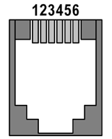 |
| 1 |
R.A. + (Right) |
| 2 |
Dec + (Up) |
| 3 |
Dec – (Down) |
| 4 |
R.A. – (Left) |
| 5 |
Common (Ground) |
| 6 |
Not connected |
|
Mechanical Specifications
C0, CG, and C1 camera head is designed to be lightweight and
compact to be easily attached even to small telescopes or
finders.
The head is CNC-machined from high-quality aluminum and black
anodized. The head itself contains USB-B 3.0 (device) connector
and standard 6-pin “autoguider” connector.
| Internal mechanical shutter |
No |
| Shortest exposure time |
125 μs |
| Longest exposure time |
Limited by chip saturation only |
| C0 head dimensions |
50 mm × 50 mm × 40.4 mm (including CS-mount adapter) |
| CG head dimensions |
50 mm × 34 mm × 68 mm (including CS-mount adapter) |
| C1 head dimensions |
57 mm × 57 mm × 47.4 mm (including CS-mount adapter) |
| Back focal distance |
12.5 mm
for 1/32 UN thread (CS-mount compatible) |
| |
18.5 mm
for M42 × 0.75
thread (T-mount) |
| C0 head weight |
115 g |
| CG head weight |
138 g |
| C1 head weight |
170 g |
Telescope/lens adapters
C0 and C1 cameras are supplied with two types of
telescope/lens adapters:
Adapter with 1/32 UN thread and
12.5 mm Back
Focal Distance (CS-mount). Adapter with M42 × 0.75 thread (T-thread)
and 18.5 mm
Back Focal Distance. This adapter also contains inner thread
1/32 UN with 12.5 mm BFD (CS-mount).
 and C1 camera with combined T-thread (M42 × 0.75) and CS-mount adapter (right)")
Comparison of C1 camera with CS- mount only adapter
(left) and C1 camera with combined T-thread (M42 × 0.75) and CS-mount
adapter (right) The CG cameras are supplied with CS-mount adapter only.

CG camera with CS-mount adapter CS-mount it compatible with vast number of CCTV lenses. If
C-mount lens has to be used (with 17.5 mm Back Focal Distance), simple 5 mm thick adapter ring can be used.
Warning: If the camera should be used with OAG for cooled
Cx cameras, short 10 mm C-to-1.25” barrel adapter has to be
used. This adapter, shipped with respective OAG, is fully
compatible with C0 and C1 camera. Note the C0 and C1
cameras with M42 × 0.75 (T-thread) adapter
cannot be used with OAG, despite the short CS-to-1.25" barrel
adapter can be attached to it. The large-diameter M42 adapter
interferes with screws fixing the camera in the OAG guider
port. This is why C0 and C1 variant with CS-mount only adapter
are still supplied. C-to-1.25” barrel adapter, compatible with standard 1.25”
eyepieces, is included into camera package. So, the C0 or C1
camera can be easily mounted into virtually every astronomical
telescope instead of an eyepiece.
The T-mount interface (also known as T-thread adapter) is
defined by thread dimensions M42 × 0.75 as well as by
55 mm Back focal Distance.
T-thread adapter for C1 cameras does not comply to the second
parameter, its BFD is only 18.5 mm. The 55 mm
BFD is not required in all applications and keeping such
relatively large BFD would make the adapter quite bulky.
Still, an extension tube with male M42 × 0.75 thread is
available. This extension tube converts the C0 or C1 camera
BFD to 55 mm, required by
numerous focal-reducers, field-flatteners, coma-correctors and
other optical elements.
There are two variants of the 55 mm BFD extension tubes
available:
, 55 mm BFD extension tube with M42 × 0.75 thread (center) and with M48 × 0.75 thread (right)")
C1 camera (left), 55 mm BFD extension tube with M42 × 0.75 thread (center)
and with M48 × 0.75 thread
(right) Also, extension tubes with bayonet interfaces for
standard photographic lenses are available:
Hint: The extension tube outer diameter is exactly
2 inches
(50.8 mm), so it
can allow using of the C0 or C1 camera with any 2" focuser
instead of 2" eyepiece. 
C1 camera with Canon EOS lens attached Tripod and metric threads
 thread and 4 metric M3 threaded holes")
C1 camera bottom contains standard 0.25" (tripod)
thread and 4 metric M3 threaded holes If the C1 camera is not attached to the telescope focuser
through its telescope/lens adapter, it can be attached to
standard photographic tripod using 0.25” thread. Another
possibility is to use 4 metric M3 threaded holes, also located
on the bottom side of the camera head.

Position of the four M3 threaded holes on the
bottom of C1 v3 camera head The threaded hole pattern (thread diameter as well as hole
mutual distances) is the same for all versions of C1 cameras.
Only the holes were 1 mm further from the camera front side on
C1 cameras version 1 and 2.

Position of the four M3 threaded holes on the
bottom of C1 camera head C0 Camera Dimensions
C0 camera head with CS-mount adapter front view
dimensions (left) and side view dimensions and Back Focal
Distance (right) C0 camera head with M42 × 0.75 adapter front
view dimensions (left) and side view dimensions and Back
Focal Distance (right) CG Camera Dimensions
CG camera head with CS-mount adapter front view
dimensions (left) and side view dimensions and Back Focal
Distance (right) C1 Camera Dimensions
C1 camera head with CS-mount adapter front view
dimensions (left) and C1 v3 side view dimensions and Back
Focal Distance (right) C1 camera head with M42 × 0.75 adapter front
view dimensions (left) and C1 v3 side view dimensions and
Back Focal Distance (right) Software support
Always use the latest versions of the system driver package for
both Windows and Linux system. Older versions of drivers may not
support new camera models (like C0) or latest versions or existing
series (like C1 version 3).
If the camera is controlled through the Moravian Camera
Ethernet Adapter, make sure the device firmware is updated to
the latest version available.
Also, always use the latest version of the SIPS software
package, older versions may not support latest cameras correctly.
If a driver for 3rd party software package is used
(e.g. ASCOM or INDI drivers), always update the driver to the
latest available version.
SIPS
Powerful SIPS (Scientific Image Processing System)
software, supplied with the camera, allows complete camera
control (exposures, cooling, filter selection etc.). Also
automatic sequences of images with different filters,
different binning etc. are supported. With full ASCOM standard
support, SIPS can be also used to control other observatory
equipment. Specifically the telescope mounts, but also other
devices (focusers, dome or roof controllers, GPS receivers
etc.).
SIPS also supports automatic guiding, including image
dithering. Both “autoguider” port hardware interface
(6-wire cable) and mount “Pulse-Guide API” guiding
methods are supported. For hi-quality mounts, capable to track
without the necessity to guide at last during one exposure,
inter-image guiding using the main camera only is
available.
")
SIPS controlling whole observatory (shown in
optional dark skin) But SIPS is capable to do much more than just camera and
observatory control. Many tools for image calibration, 16 and
32 bit FITS file handling, image
set processing (e.g. median combine), image transformation,
image export etc. are available.
SIPS handles FITS files, supports image calibration
and processing As the first “S” in the abbreviation SIPS means
Scientific, the software supports astrometric image reduction
as well as photometric processing of image series.
SIPS focuses to advanced astrometric and
photometric image reduction, but also provides some very
basic astro-photography processing SIPS software package is freely available for download from this www site. All functions
are thoroughly described in the SIPS User's Manual, installed
with every copy of the software.
Automatic guiding
SIPS software package allows automatic guiding of the
astronomical telescope mounts using separate guiding
camera. Proper and reliable automatic guiding utilizing
the computational power of Personal Computer (e.g.
calculation of star centroid allows guiding with sub-pixel
precision) is not simple task. Guiding complexity
corresponds to number of parameters, which must be entered
(or automatically measured).

The SIPS “Guider” tool window The “Guiding” tool allows switching of
autoguiding on and off, starting of the automatic
calibration procedure and recalculation of autoguiding
parameters when the telescope changes declination without
the necessity of new calibration. Also swapping of the
German Equatorial mount no longer requires new autoguider
calibration. There is also a graph showing time history of
guide star offsets from reference position in both axes.
The length of graph history as well as the graph range can
be freely defined, so the graph can be adjusted according
to particular mount errors and periodic error period
length. Complete log of calibration procedure, detected
offsets, correction pulses etc. is also shown in this
tool. The log can by anytime saved to log file.
An alternative to classic autoguiding is the
inter-image guiding, designed for modern mounts, which are
precise enough to keep tracking with sub-pixel precision
through the single exposure, and irregularities only
appear on the multiple-exposure time-span. Inter-image
guiding then performs slight mount position fixes between
individual exposures of the main camera, which eliminates
“traveling” of the observed objects through the
detector area during observing session. This guiding
method uses main imaging camera, it does not use another
guiding camera and naturally does not need neither OAG nor
separate guiding telescope to feed the light into it.

Inter-image guiding controls in the
Guiding tab of the Imager Camera tool
window Advanced reconstruction of color information of
single-shot-color cameras
Color sensors have red, green and blue filters applied
directly on individual pixels (so-called Bayer mask).
Every pixel registers light of particular color only
(red, green or blue). But color image should contain all
three colors for every pixel. So it is necessary to
calculate missing information from values of neighboring
pixels.
There are many ways how to calculate missing color
values — from simple extending of
colors to neighboring pixels (this method leads to coarse
images with visible color errors) to methods based on
bi-linear or bi-cubic interpolation to even more advanced
multi-pass methods etc.
Bi-linear interpolation provides significantly better
results than simple extending of color information to
neighboring pixels and still it is fast enough. But if the
telescope/lens resolution is close to the size of
individual pixels, color artifacts appear close to fine
details, as demonstrated by the image below left.
The above raw image with colors calculated
using bi-linear interpolation (left) and the same raw
image, but now processed by the multi-pass de-mosaic
algorithm (right) Multi-pass algorithm is significantly slower compared
to single-pass bi-linear interpolation, but the resulting
image is much better, especially in fine details. This
method allows using of color camera resolution to its
limits.
SIPS offers choosing of color image interpolation
method in both “Image Transform” and “New Image
Transform” tools. For fast image previews or if the
smallest details are significantly bigger than is the
pixel size (be it due to seeing or resolution of the used
telescope/lens) the fast bi-linear interpolation is good
enough. But the best results can be achieved using
multi-pass method.
Drivers for 3rd party programs
Regularly updated Sofware Development Kit for Windows allows to
control all cameras from arbitrary applications, as well as
from Python scripts etc.
There are ASCOM standard drivers available together with
native drivers for some 3rd party programs (for
instance, TheSkyX, AstroArt, etc.). Visit the download page of this server to see a list of
all supported drivers.
Libraries and INDI standard drivers for 32-bit and 64-bit
Linux working on x86 and ARM processors are available as well. Also drivers for TheSkyX
running on macOS are supplied with all cameras.
First light images
The very first prototype of C1-3000 camera was used by
renowned astro-photographer Martin Myslivec. He used the Borg 77ED
refractor telescope on the EQ6 mount co capture several unguided
exposures. Despite we understand Martin is highly skilled and
experienced astro-photographer, the performance of C1 camera is
very good also for deep-sky imaging.
C1-3000 first light: M31 Great Andromeda galaxy (left),
M42 Great Orion nebula (center) and nebulosity around stars in
M45 Pleiades open cluster (right) The M31 Great Andromeda galaxy is a stack of 197
exposures 20 s long (approximately
1 hour and 5 minutes of total exposure time). No image processing
was performed beside individual frame calibration and slightly
non-linear stretching.
The M42 Great Orion nebula image was combined from two
sets of exposures (kind of HDR image processing). Faint
nebulosity, far from the image center, was acquired using 100
exposures 20 s long (approximately 33 minutes of total exposure
time). The very bright central part of the nebula was captured
with only 2 s long exposures (again 100 of them), which leads to
approximately 3 minutes of total exposure time. The very short
exposures allowed to perfectly capture the 4 central stars (called
Trapezium) without over-exposing them.
The image of M45 Pleiades is a combination of 218
exposures 20 s long (approximately 1 hour and 12 minutes of total
exposure time). Again, no image processing was performed, only the
calibration and slight non-linearly stretch was performed.
Sun in the Hα spectral line
Martin Myslivec used his global-shutter C1-5000 based
camera to acquire the Sun in the Hα line.
See what the C1 camera can achieve on the Sun.
| 