- C3 Series CMOS Cameras
- C3 Camera Overview
- CMOS Sensor and Camera Electronics
- Cooling and power supply
- Mechanical Specifications
- Back focal distance
- Optional accessories
- Software support
- Shipping and Packaging
- Image Gallery
C3 Camera Overview
Mechanical design of the C3 series of astronomical CMOS cameras
inherits from earlier CCD-based G3 Mark II cameras, which makes
the C3 camera line fully compatible with vast range of telescope
adapters, off-axis guider adapters, filter wheels, Ethernet
adapters, guiding cameras etc.
Rich software and driver support allow usage of C3 camera
without a necessity to invest into any 3rd party software package
thanks to included free SIPS software package. However, ASCOM (for
Windows) and INDI (for Linux) drivers and Linux driver libraries
are shipped with the camera, provide the way to integrate C3
camera with broad variety of camera control programs.
The C3 cameras are designed to work in cooperation with
a host Personal Computer (PC). As opposite to digital still
cameras, which are operated independently on the computer, the
scientific cooled cameras usually require computer for operation
control, image download, processing and storage etc. To operate
the camera, you need a computer which:
Is compatible with a PC standard and runs modern 32 or
64-bit Windows operating system. Is an x86 or ARM based computer and runs 32 or 64-bit
Linux operating system. Support for x64 based Apple Macintosh computers is also
included.
C3 cameras are designed to be attached to host PC through very
fast USB 3.0 port. While C3 cameras remain compatible with older
(and slower) USB 2.0 interface, image download time is
significantly longer.
Alternatively, it is possible to use the Moravian Camera
Ethernet Adapter device. This device can connect up to four
Cx (and CCD based Gx) cameras of any type (not only C3, but also
C1, C2 and C4) and offers 1 Gbps and 10/100 Mbps Ethernet
interface for direct connection to the host PC. Because the PC
then uses TCP/IP protocol to communicate with the cameras, it is
possible to insert WiFi adapter or other networking device to the
communication path.
Hint: Please note that the USB standard allows usage of cable
no longer than approx. 5 meters and USB 3.0 cables are even
shorter to achieve very fast transfer speeds. On the other side,
the TCP/IP communication protocol used to connect the camera over
the Ethernet adapter is routable, so the distance between camera
setup and the host PC is virtually unlimited. Download speed is naturally significantly slower when camera is
attached over Ethernet adapter, especially when compared with
direct USB 3 connection.
The C3 cameras need an external power supply to operate. It is
not possible to run the camera from the power lines provided by
the USB cable, which is common for simple imagers. C3 cameras
integrate highly efficient CMOS sensor cooling, shutter and
possibly filter wheel, so their power requirements significantly
exceed USB line power capabilities. On the other side separate
power source eliminates problems with voltage drop on long USB
cables or with drawing of laptop batteries etc.
Also note the camera must be connected to some optical system
(e.g. the telescope) to capture images. The camera is designed for
long exposures, necessary to acquire the light from faint objects.
If you plan to use the camera with the telescope, make sure the
whole telescope/mount setup is capable to track the target object
smoothly during long exposures.
C3 camera head is designed to be easily used with a set of
accessories to fulfill various observing needs. The camera head
itself is manufactured in several variants.
First, there are variants differing in the cooling
performance:
Second, there are variants differing in filter wheel
control:
Camera with Internal filter wheel. Camera with control port for External filter wheel. This
model allows attachment of several variants of external filter
wheels with various number of filter positions and
sizes.
C3 camera model with Internal filter wheel accepts two
sizes of filters:
There are three sizes of the External filter wheels,
capable to accept various sizes of filters, available for the C3
cameras:
Small “S” size wheel for 10 unmounted filters
D36 mm. Small “S” size wheel for 7 unmounted filters
D50 mm or filters in 2” threaded cells. Small “S” size wheel for 5 unmounted square
filters 50 × 50 mm. Middle “M” size wheel for 10 unmounted filters
D36 mm. Middle “M” size wheel for 7 unmounted filters
D50 mm or filters in 2” threaded cells. Middle “M” size wheel for 5 unmounted square
filters 50 × 50 mm. Large “L” size wheel for 9 unmounted D50 mm or
filters in 2” threaded cells. Large “L” size wheel for 7 unmounted square
filters 50 × 50 mm.
Warning: Both Internal and External filter wheels for D36 mm
filters can be used with C3 camera equipped with APS size sensors
only. Cameras with “Full-frame” sensors (24 × 36mm) cannot use such small
filters. Please note the camera head is designed to either
accept Internal filter wheel or to be able to connect to the
External filter wheel, but not both. If the Internal filter wheel
variant is used, External filter wheel cannot be
attached. And third, there are two sizes of adjustable adapters,
which can be used with C3 cameras:
Small “S” adapters, compatible with C2 cameras,
are used for e.g. M48 × 0.75 and
M42 × 0.75 threaded adapters, Nikon
bayonet adapter, 2” barrel adapter etc. Large “L” adapters, compatible with C4 cameras,
intended for large diameter attachments between camera and
telescope, e.g. M68 × 1 threaded
adapter or G3-OAG, which is also equipped with M68 × 1 thread.
Adjustable adapters are mounted on adapter base when
camera with internal filter wheel or camera without any filter
wheel is used or directly on the external filter wheel front
surface. This means both “S” and “L” adapter bases can be
mounted on any camera, but external filter wheels are made for
one particular adapter size only:
Camera head and numerous accessories comprise imaging system,
capable to be tailored for many applications.

Schematic diagram of C3 camera with “S” size
adapter system components 
Schematic diagram of C3 camera with “L” size
adapter system components Components of C3 Camera system include:
C3 camera head with Internal Filter Wheel C3 camera head with Internal Filter Wheel and Enhanced
Cooling option C3 camera head capable to control External Filter
Wheel C3 camera head capable to control External Filter Wheel
with Enhanced Cooling option 1.75” dovetail rail for C3 camera head Moravian Camera Ethernet Adapter (x86 CPU) Moravian Camera Ethernet Adapter (ARM
CPU) 7-positions internal filter wheel for unmounted D36 mm
filters 5-positions internal filter wheel for 2”/D50 mm
filters 10-positions filter wheel for “S” or “M”
housing for unmounted D36 mm filters 7-positions filter wheel for “S” or “M”
housing for 2”/D50 mm filters 5-positions filter wheel for “S” or “M”
housing for 50 × 50 mm square
filters External Filter Wheel “S” size (5, 7 or 10
positions) M42 × 0.75
(T-thread) or M48 × 0.75 threaded
“S” size adapters, 55 mm
BFD Canon EOS bayonet lens “S” size adapter Nikon bayonet lens “S” size adapter External Filter Wheel “M” size (5, 7 or 10
positions) External Filter Wheel “L” size (7 or 9
positions) 9-positions filter wheel for “L” housing for
2”/D50 mm filters 7-positions filter wheel for “L” housing for
50 × 50 mm square filters C1 auto-guiding camera M68 × 1 threaded “L”
size adapter, 47.5 mm BFD Canon EOS bayonet lens “L” size adapter Off-Axis Guider with M68 × 1
thread, 61.5 mm BFD
CMOS Sensor and Camera Electronics
C3 cameras are equipped with Sony IMX rolling shutter
back-illuminated CMOS detectors with
3.76 × 3.76 μm square pixels. Despite the relatively small pixel
size, the full-well capacity over 50 ke- rivals the full-well
capacity of competing CMOS sensors with much greater pixels and
even exceeds the full-well capacity of CCD sensors with comparable
pixel size.
The used Sony sensors are equipped with 16-bit ADCs (Analog to
Digital Converters). 16-bit digitization ensures enough resolution
to completely cover the sensor exceptional dynamic range.
Both IMX571 (used in C3-26000) and IMX455 (used in
C3-61000) sensors are supplied in two variants:
Consumer grade sensors. The sensor manufacturer
(Sony Semiconductor Solutions Corporation) limits their usage to
consumer still cameras only with operation time max. 300 hours
per year. Industrial grade sensors, intended for devices
operating 24/7.
All sensor characteristics (resolution, dynamic range,
…) are equal, sensors differ only in target applications and
usage time. C3 is technically digital still camera, only
specialized for astronomy. If it is also “consumer”
camera strongly depends on users. Cameras used for causal
imaging (when weather permits) only rarely exceeds 300 hours of
observing time per year. Cameras permanently installed on
observatories, utilizing every clear night and possibly located
on mountain sites with lots of clear nights exceed the
300 hours/year within a couple of months. This is why C3 cameras
are offered in two variants:
C3-26000 and C3-61000 with consumer
grade sensors, intended for max. 300 hours a year
operation. C3-26000 PRO and C3-61000 PRO with
industrial grade sensors.
C3 camera models with consumer-grade sensors include:
| Model |
C3-26000 |
C3-61000 |
C3-26000C |
C3-61000C |
| CMOS sensor |
IMX571 |
IMX455 |
IMX571 |
IMX455 |
| Sensor grade |
Consumer |
Consumer |
Consumer |
Consumer |
| Color mask |
None |
None |
Bayer RGBG |
Bayer RGBG |
| Resolution |
6252 × 4176 |
9576 × 6388 |
6252 × 4176 |
9576 × 6388 |
| Pixel size |
3.76 × 3.76 μm |
3.76 × 3.76 μm |
3.76 × 3.76 μm |
3.76 × 3.76 μm |
| Sensor size |
23.51 × 15.70 mm |
36.01 × 24.02 mm |
23.51 × 15.70 mm |
36.01 × 24.02 mm |
C3 camera models with industrial-grade sensors include:
| Model |
C3-26000 PRO |
C3-61000 PRO |
C3-26000C PRO |
C3-61000C PRO |
| CMOS sensor |
IMX571 |
IMX455 |
IMX571 |
IMX455 |
| Sensor grade |
Industrial |
Industrial |
Industrial |
Industrial |
| Color mask |
None |
None |
Bayer RGBG |
Bayer RGBG |
| Resolution |
6252 × 4176 |
9576 × 6388 |
6252 × 4176 |
9576 × 6388 |
| Pixel size |
3.76 × 3.76 μm |
3.76 × 3.76 μm |
3.76 × 3.76 μm |
3.76 × 3.76 μm |
| Sensor size |
23.51 × 15.70 mm |
36.01 × 24.02 mm |
23.51 × 15.70 mm |
36.01 × 24.02 mm |
Camera Electronics
CMOS camera electronics primary role, beside the sensor
initialization and some auxiliary functions, is to transfer
data from the CMOS detector to the host PC for storage and
processing. So, as opposite to CCD cameras, CMOS camera design
cannot influence number of important camera features, like the
dynamic range (bit-depth of the digitized pixels).
Sensor linearity
The sensors used in C3 cameras show very good linearity in
response to light. This means the camera can be used for
advanced research projects, like the photometry of variable
stars and transiting exoplanets etc.

Response of IMX455 sensor in 16-bit mode Download speed
C3 cameras are equipped with on-board RAM, capable to hold
several full-resolution frames. Downloading of the image to
the host computer thus does not influence image digitization
process, as the download only transfers already digitized
images from camera memory.
Time needed to digitize and download single full frame
depends on USB connection type.
| Model |
C3-26000 |
C3-61000 |
| Full-frame, USB 3.0 (5 Gbps) |
0.22 s |
0.44 s |
| Full-frame, USB 2.0 (480 Mbps) |
1.16 s |
2.73 s |
If only a sub-frame is read, time needed to digitize and
download image is naturally lower. However, the download time
is not cut proportionally to number of pixels thanks to some
fixed overhead time, independent on the sub-frame
dimensions.
| Model |
C3-26000 |
C3-61000 |
| 1024 × 1024
sub-frame, USB 3.0 (5 Gbps) |
0.03 s |
0.05 s |
| 1024 × 1024
sub-frame, USB 2.0 (480 Mbps) |
0.06 s |
0.06 s |
Warning: Download times stated above are valid for cameras
with firmware version 3.3 and later. Older firmware download
times were approximately 30% longer. Hint: The driver is sometimes forced to read bigger
portions of the sensor than the user defined because of a
sub-frame position and dimension limitations imposed by the
sensor hardware. Sometimes it is even necessary to read the
whole sensor. It is recommended to click the Adjust
Frame button in the Frame tab of the SIPS camera
control tool. The selected frame dimensions are then adjusted
according to sensor limitations. Adjusted frame is then read
from the sensor, without a necessity to read a bigger portions
or even whole sensor and crop image in firmware. C3 camera electronics supports in-camera 2 × 2 binning. If this binning mode is used,
download speed increases because of less amount of data read
from camera.
| Model |
C3-26000 |
C3-61000 |
| Full-frame 2 × 2
binning, USB 3.0 (5 Gbps) |
0.16 s |
0.30 s |
| Full-frame 2 × 2
binning, USB 2.0 (480 Mbps) |
0.29 s |
0.69 s |
Warning: The in-camera binning is supported by firmware
version 3.3 and later. Download speed when using the Moravian Camera Ethernet
Adapter depends if the 100 Mbps or 1 Gbps Ethernet is used, if
USB 2 or USB 3 is used to connect camera to Ethernet Adapter
device, but also depends on the particular network utilization
etc. When the camera is connected to the Ethernet Adapter
using USB 3 and 1 Gbps Ethernet is directly connected to the
host PC, download time of the C3-61000 full frame is approx.
2.5 s.
Camera gain
Sensors used in C3 cameras offer programmable gain from 0
to 36 dB, which translates to the output signal multiplication
from 1× to 63×.
Camera driver accepts gain as a number in the range 0 to
4030, which corresponds directly to sensor register value.
This number does not represent gain in dB nor it is an exact
gain multiply. However, the driver offers a function, which
transforms the gain numerical value to gain expressed in dB as
well as multiply. Some selected values are shown in the
table:
| Gain number |
Gain in dB |
Gain multiply |
| 0 |
0.00 |
1.00× |
| 1000 |
2.34 |
1.32× |
| 2000 |
5.82 |
1.95× |
| 3000 |
11.46 |
3.74× |
| 4000 |
32.69 |
43.11× |
| 4030 |
35.99 |
63.00× |
Conversion factors and read noise
Generally, many sensor characteristics depend on the used
gain. Also, the used sensors employ two conversion paths. One
path offers very low read noise, but cannot utilize full
sensor dynamic range. Another conversion path offers maximum
pixel capacity, but at the price of higher read noise. The
cross point is set to gain 3×
(approx. 10 dB), where the full
well capacity drops from more than 50 ke- to ~17 ke-. The read noise then drops from
~3.2 e- RMS to
~1.5 e- RMS.
| Gain number |
Gain in dB |
Gain multiply |
Conversion factor |
Read noise RMS |
Full well capacity |
| 0 |
0.0 dB |
1× |
0.80 e-/ADU |
3.51 e- |
52,800 e- |
| 2749 |
9.7 dB |
3× |
0.26 e-/ADU |
3.15 e- |
17,000 e- |
| 2750 |
9.7 dB |
3× |
0.26 e-/ADU |
1.46 e- |
17,000 e- |
| 4030 |
36.0 dB |
63× |
0.012 e-/ADU |
1.28 e- |
800 e- |
Sensor dynamic range, defined as full well capacity
divided by read noise, is greatest when using gain 0,
despite somewhat higher read noise:
At gain = 0, dynamic range is
52,800 / 3.51 = 15,043× At gain = 2750, dynamic range is
17,000 / 1.46 = 11,644×
Also, it is worth noting that in reality the noise floor is
not always defined by read noise. Unless the camera is used
with very narrow narrow-band filter (with FWHM only a few nm)
and under very dark sky, the dominant source of noise is the
sky glow. When the noise generated by sky glow exceeds
approximately 4 e- RMS, extremely
low read noise associated with gain set to 2750 or more is not
utilized and dynamic range is unnecessarily limited by the
lowered full well capacity.
So, which gain settings is the best? This depends
on the particular task.
Gain set to 2750 can be utilized if imaging through
narrow-band filter with appropriately short exposures, so
the background noise does not exceed the read noise. This is
typical for aesthetic astro-photography, where the lowered
full well capacity does not negatively influence the result
quality. But even without narrow-band filters, the
extremely low read noise allows stacking of many short
exposures without unacceptable increase of the stacked image
background noise, caused by accumulation of high read noise
of individual exposures. Gain set to 0 offers maximum full well capacity and
the greatest sensor dynamic range, which is appreciated
mainly in research applications. Pass-bands of filters used
for photometry are relatively wide and dominant source of
noise is the sky glow. But also for RGB images, used
for aesthetic astro-photography, higher dynamic range allows
longer exposures while the bright portions of the nebulae
and galaxies still remain under saturation and thus can be
properly processed.
Binning
The camera driver and user’s applications offer wide
variety of binning modes up to 4 × 4 pixels as well as all combinations of
asymmetrical binning modes 1 × 2,
1 × 3, 1 × 4, 2 × 4
etc. To allow such flexibility, binning is performed only in
the camera driver (software binning) and does not rely on the
limited capabilities of the hardware binning.
The negative side of software binning is the same download
time like in the case of full-resolution 1 × 1 mode. For typical astronomy usage, the
small fraction of second download time is irrelevant, but for
applications sensitive to download time, the hardware
2 × 2 binning can be useful.
Hardware binning
C3 camera implements 2 × 2
binning mode in hardware in addition to normal 1 × 1 binning.
Warning: Hardware binning is supported by camera
firmware version 3.3 and later. The Windows SDK supports
the hardware binning from version 4.11 and the SIPS
software package from version 3.33. Hardware binning can be turned on and off using the
parameter HWBinning in the 'cXusb.ini'
configuration file, located in the same directory like the
'cXusb.dll' driver DLL file itself.
[driver]
HWBinning = true
When the HWBinning parameter is set to
true, the in-camera hardware binning is used. This mode
brings faster download time, but also introduces several
restrictions:
Maximal binning is limited to 2 × 2, higher binning modes are not
available. Asymmetrical binning modes (1 × 2, 2 × 1, ...) are not allowed.
Adding vs. averaging pixels
The traditional meaning of pixel binning implies adding
of binned pixels. This originated in CCD sensors, where
pixel charges were literally poured together within the
sensor horizontal register and/or the output node.
For CMOS sensors with full 16-bit dynamic resolution,
the negative side of binning is limiting of the sensor
dynamic range, as for instance only 1/4 of maximum charge
in each of the 2 × 2 binned
pixels leads to saturation of resulting pixel. CCDs
eliminated this effect to some extend by increasing of the
charge capacity of the output node and also by decreasing
of the conversion factor in binned modes. But such
possibilities are not available in CMOS detectors.
In theory, the resulting S/N ratio of binned
pixel remains the same regardless if we add or average
them. Let's take for example 2 × 2 binning:
If we add 4 pixels, signal increases 4-times and
noise increases 2-times — three
additive operations increase noise by
√((√2)^2+(√2)^2 ). Resulting S/N
increases 2-times, but only until the sum of all pixels
is lower than the pixel capacity. If we average 4 pixels, signal remains the same
but the noise is lowered to 1/2 as noise is averaged
√((√2)^2+(√2)^2 )/4. Resulting S/N
also increases 2-times, but only until the noise
decreases to lowest possible 1-bit of dynamic
range.
As the C3 camera read noise in the maximum dynamic
range (gain 0) is around 3.5 ADU, halving
it in 2 × 2 binning mode
still keeps the read noise above the lower 1-bit limit and
at the same time binned pixel will not saturate. For
higher binning modes, the noise approaches lower limit,
but averaging pixels still protects from pixel saturation,
which is more important than limiting of S/N.
If we take into account that the image background noise
is only rarely defined by the read noise of the sensor, as
the noise caused by background sky glow is typically much
higher, for 16-bit camera averaging pixels is definitely
the better way to bin pixels compared to just adding them.
This is why both software and hardware binning modes in
the C3 cameras are by default implemented as averaging of
pixels, not summing.
However, both software and hardware binning modes can
be switched to sum binned pixels instead of average them
by the BinningSum parameter in the
'cXusb.ini' configuration file:
[driver]
BinningSum = true
Let’s note there is one more possibility to bin
pixels — in the application
software. This time binning is not performed in camera
hardware nor in the camera driver. Full resolution
1 × 1 image is downloaded
from the camera and software itself then performs binning.
The SIPS software adds pixels instead of averaging them,
but at the same time SIPS converts images from 16-bit to
32-bit dynamic range. This means S/N of the binned images
always increases, pixels never saturate and read noise
newer approaches lower limit. The negative side of this
option is two-time bigger images.
Binning in photometry
Saturated pixels within bright stars are no issue for
aesthetic astro-photography, but photometry measurement is
invalid if any pixel within the measured object reaches
maximum value, because it is not possible to determine the
amount of lost flux. Software performing photometry (e.g.
the SIPS Photometry tool) should detect saturation value
and invalidate entire photometric point not to introduce
errors.
But binning efficiently obliterates the fact that any
of the binned pixels saturated (with the exception of all
binned pixels reached saturation value). So, using of
binning modes for research applications (photometry and
astrometry) can lead to errors caused by lost flux in
saturated pixels, which cannot be detected by the
processing software due to binning.
This is why the behavior of both software and hardware
binning modes is user-configurable through the
BinningSaturate parameter in the
'cXusb.ini' configuration file:
[driver]
BinningSaturate = true
If the BinningSaturate parameter is set to
true, resulting binned pixel is set to saturation value if
any of the source pixels is saturated. For aesthetic
astro-photography, keeping this parameter false could
result into slightly better representation of bright star
images, but for research applications, this parameter
should always be set to true.
Note the BinningSum and
BinningSaturate parameters have any effect if the
camera firmware version is 5.5 or later. Prior firmware
versions just averaged binned pixels and the pixel
saturation was not taken into account when hardware (in
camera) binning was used.
The earlier camera drivers, performing software
binning, also used pixel averaging for binning, but
handled the saturated pixels like the
BinningSaturate parameter is true.
Both above mentioned configuration parameters
require at last the software/drivers version:
SIPS version 3.33 Moravian Camera SDK version 4.11 ASCOM drivers version 5.13 Linux INDI drivers version 1.9-2 Linux libraries version 0.7.1 macOS libraries version 0.6.1 TheSkyX Windows/Linux/macOS version 3.4 AstroArt drivers version 4.3
If the camera is used through the Moravian Camera
Ethernet Adapter, it’s firmware must be updated to version
53 or newer.
Exposure control
The shortest theoretical exposure time of the C3
cameras depends on the used sensor type:
However, such short exposures have no practical
application, especially in astronomy. The camera firmware
rounds exposure time to a multiply of 100 μs intervals, so in
reality the shortest exposure time of both camera models is
200 μs.
There is no theoretical limit on maximal exposure length,
but in reality, the longest exposures are limited by
saturation of the sensor either by incoming light or by dark
current (see the following chapter about sensor cooling).
Warning: Please note the short exposure timing is properly
handled in the camera firmware version 6.5 and
later. Mechanical shutter
C3 cameras are equipped with mechanical shutter, which
is very important feature allowing unattended observations
(fully robotic or just remote setups). Without mechanical
shutter, it is not possible to automatically acquire dark
frames, necessary for proper image calibration etc.
Mechanical shutter in the C3 cameras is designed to be
as reliable as possible, number of open/close cycles is
virtually unlimited, because there are no surfaces rubbing
against each other. The price for high reliability is slow
shutter motion. Luckily, mechanical shuttering is not
necessary for exposure control, only for taking dark
frames and possibly bias frames — all used CMOS sensors are equipped with
electronic shuttering.
Camera firmware optimizes the shutter operation to
avoid unnecessary movements. If a series of light images
is taken immediately one after another, the shutter
remains open not to introduce quite significant delay of
the close/open cycle between each pair of subsequent light
images. In the case next image has to be dark or bias
frame, shutter closes prior to dark frame exposure and
vice versa — shutter remains closed
if a series of dark frames is acquired and opens only
prior to next light frame. If no exposure is taken for a
few seconds while the shutter is open (this means after a
light image exposure), camera firmware closes the shutter
to cover the sensor from incoming light.
GPS exposure timing
C3 cameras can be equipped with GPS receiver module
(see the Optional Accessories chapter). The primary
purpose of the GPS receiver is to provide precise times of
exposures taken with the camera, which is required by
applications dealing with astrometry of fast-moving
objects (fast moving asteroids, satellites, and space
debris on Earth orbit, …).
The GPS module needs to locate at last 5 satellites to
provide exposure timing information. Geographic data are
available if only 3 satellites are visible, but especially
the mean sea level precision suffers if less than 4
satellites are used.
The camera SDK provides functions, allowing users to
access precision exposure times as well as geographics
location. The SIPS software package main imaging camera
control tool window contains the “GPS” tab, which
shows the state of the GPS fix.
Determination of exact exposure time is quite
complicated because of the rolling-shutter nature of the
used sensors. Camera driver does all the calculations
and returns the time of the start of exposure of the
first line of the image. Still, users interested in
precise exposure timing need to include several
corrections into their calculations:
Individual image lines are exposed sequentially.
The time difference between start of exposure of two
subsequent lines is fixed for every sensor type: If the image is binned, single line of resulting
image contains signal from multiple added (or averaged)
lines, each with different exposure time start. The
exposure start of individual lines of the binned images
differs by the single line time difference, multiplied
by the vertical binning factor. If only a sub-frame is read, it must be
considered that the sensor imposes some restrictions to
the sub-frame coordinates. If the required sub-frame
coordinates violate the sensor-imposed rules, camera
driver enlarges the sub-frame region to fully contain
desired sub-frame and then crops it by software. The
provided start exposure time then concerns the first
line actually read from the camera, not the first line
of the resulting (software cropped) image. For
instance, the y-coordinate of the sub-frame must not be
lower than 25 lines. If a sub-frame with lower
y-coordinate is asked by the user, whole frame is read
and cropped by software. Note the camera SDK offers
function AdjustSubFrame, which returns the
smallest sub-frame, fully containing the requested
sub-frame, but also fulfilling the sensor-imposed
sub-frame coordinate restriction. If adjusted sub-frame
is read, no software cropping occurs and image exposure
time concerns the first line of the image. The SIPS
software offers the “Adjust Frame” button, which
adjusts defined sub-frame.
Warning: Please note the precise exposure timing is
properly handled in the camera firmware version 7.10 and
later. Always use the latest camera drivers (ASCOM or Camera
SDK DLLs in Windows, INDI or libraries in Linux) available
on the web. Also, always update the firmware in the
Moravian Camera Ethernet Adapter if the camera is
connected over Ethernet.
Cooling and power supply
Regulated thermoelectric cooling is capable to cool the CMOS
sensor from 40 to 45 °C below ambient temperature, depending on
the camera type. The Peltier hot side is cooled by fans. The
sensor temperature is regulated with ±0.1 °C precision. High
temperature drop and precision regulation ensure very low dark
current for long exposures and allow proper image calibration.
C3 cameras are available in two variants, differing in
the cooling performance:
Standard cooling cameras achieve regulated
temperature difference up to 40 °C under environment
temperature. Enhanced cooling cameras can regulate
temperature up to 45 °C under environment temperature. Compared
to standard variant, enhanced cooling cameras are somewhat
bulkier due to bigger heat sink, slightly heavier and somewhat
noisier because of more powerful fans. Liquid cooling cameras with a liquid heat
exchanger instead of air heatsink and fans.
Comparison of the C3 standard cooling camera and
enhanced cooling version Comparison of the C3 enhanced air cooling version with
the liquid cooling version The cooling performance depends on the environmental conditions
and also on the power supply. If the power supply voltage drops
below 12 V, the maximum temperature
drop is lower.
| Sensor cooling |
Thermoelectric (Peltier modules) |
| Standard cooling ΔT |
40 °C below ambient maximum |
| |
35 °C below ambient typical |
| Enhanced cooling ΔT |
45 °C below ambient maximum |
| |
40 °C below ambient typical |
| Regulation precision |
0.1 °C |
| Hot side cooling |
Air cooling (two fans) |
| |
Optional liquid coolant heat exchanger |
Chip cooling specifications Standard cooling C3-61000 (left) and Enhanced cooling
C3-61000EC (right) cameras reaching -40°C and -45°C sensor
temperature Liquid cooling option
Cameras with liquid heat exchangers have two couplings on
the back for the coolant inlet and outlet hoses. The
complementary coupling parts, intended for the hoses, are
supplied with the camera. It is up to the user to provide
liquid coolant to remove heat from Peltier hot side.
Warning: The liquid-cooled cameras do not provide other
means of heat removal, but the liquid coolant. There is no
additional air heatsink nor fans for air
cooling. The back side of the C3-61000LC camera with coolant
inlet and outlet couplings The dimensions of the liquid-cooled cameras body equal to
dimensions of the Enhanced cooling variant, which means the
camera body is 11 mm thicker compared to standard air-cooling
version.
Overheating protection
The C3 cameras are equipped with an overheating protection
in their firmware. This protection is designed to prevent the
Peltier hot side to reach temperatures above ~50°C sensor
cooling is turned off to stop heat generation by the hot side
of the Peltier TEC modules.
Turning the overheating protection on results in a drop in
cooling power, a decrease in the internal temperature of the
camera and an increase in the temperature of the sensor.
However, when the camera cools its internals down below the
limit, cooling is turned on again. If the environment
temperature is still high, camera internal temperature rises
above the limit an overheating protection becomes active
again.
Power supply
The 12 V DC power supply enables camera operation
from arbitrary power source including batteries, wall adapters
etc. Universal 100-240 V
AC/50-60 Hz, 60 W “brick” adapter is supplied with
the camera. Although the camera power consumption does not
exceed 50 W, the 60 W power supply ensures noise-free
operation.
| Camera power supply |
12 V DC |
| Camera power consumption |
<8 W without cooling |
| |
47 W maximum cooling |
| Power plug |
5.5/2.5 mm, center
+ |
| Adapter input voltage |
100-240 V AC/50-60 Hz |
| Adapter output voltage |
12 V DC/5 A |
| Adapter maximum power |
60 W |
Power supply specification Warning: The power connector on the camera head uses
center-plus pin. Although all modern power supplies use this
configuration, always make sure the polarity is correct if
other than the supplied power source is used. 
12 V DC/5 A power supply adapter for C3
camera Mechanical Specifications
Compact and robust camera head measures only 154 × 154 × 65 mm (approx.
6 × 6 × 2.6 inches) for
the model with standard cooling. Enhanced cooling increases camera
depth by 11 mm.
 and with enhanced cooling (left), camera with internal filter wheel and standard cooling (right) and with enhanced cooling (far right)")
C3 camera without filters and standard cooling (far
left) and with enhanced cooling (left), camera with internal
filter wheel and standard cooling (right) and with enhanced
cooling (far right) The head is CNC-machined from high-quality aluminum and black
anodized. The head itself contains USB-B (device) connector and
12 V DC
power plug, no other parts, except a “brick” power supply,
are necessary. Another connector allows control of optional
external filter wheel. Integrated mechanical shutter allows
automatic dark frame exposures, which are necessary for
unattended, robotic setups.
| Internal mechanical shutter |
Yes, blade shutter |
| Standard cooling camera dimensions |
154 mm × 154 mm × 65 mm
(without filters) |
| |
154 mm × 154 mm × 77.5 mm (internal wheel) |
| Enhanced cooling camera dimensions |
154 mm × 154 mm × 76 mm
(without filters) |
| |
154 mm × 154 mm × 88.5 mm (internal wheel) |
| Back focal distance |
33.5 mm
(base of adjustable adapters) |
| Standard cooling camera weight |
1.6 kg
(without filter wheel) |
| |
1.9 kg
(with internal filter wheel) |
| |
2.5 kg
(with “S” external filter wheel) |
| |
2.5 kg
(with “M” external filter wheel) |
| |
2.8 kg
(with “L” external filter wheel) |
| Enhanced cooling camera weight |
1.8 kg
(without filter wheel) |
| |
2.1 kg
(with internal filter wheel) |
| |
2.7 kg
(with “S” external filter wheel) |
| |
2.7 kg
(with “M” external filter wheel) |
| |
3.0 kg
(with “L” external filter wheel) |
Mechanical specification Camera front view
C3 camera front cross-section is the same for cameras with
Internal Filter Wheel or without filter wheel, as well as for
variants with standard and enhanced cooling.

C3 camera head front view dimensions Camera without filter wheel
C3 camera head side view dimensions C3 camera with Enhanced cooling head side view
dimensions Camera with Internal Filter Wheel
C3 camera with Internal Filter Wheel head side view
dimensions C3 camera with Internal Filter Wheel and Enhanced
cooling head side view dimensions Camera with the “S” size External filter
wheel

C3 camera head with the “S” External filter
wheel front view dimensions C3 camera head with “S” External filter
wheel side view dimensions The “M” and “L” sized External Filter Wheels
diameter is greater (see External Filter Wheel User's Guide),
but the back focal distance of all external filter wheels is
identical.
Enhanced cooling C3 camera head with “S”
External filter wheel side view dimensions Back focal distance
The stated back focal distances (BFD) include corrections for
all optical elements in the light path (cold chamber optical
window, sensor cover glass, ...), fixed in the camera body. So,
stated values are not mechanical, but optical back focal
distances. However, no corrections for filters are included, as
the thicknesses of various filters are very different.
C3 cameras are manufactured in many variants and can be
connected with various accessories, which leads to many possible
back focal distance values.
There are two groups of the telescope and lens
adapters, differing in back focal distance definition:
Adapters without strictly defined BFD. These
adapters are designed to provide as low BFD as
possible. Adapter with defined BFD. These adapters are
typically intended for optical correctors (field flatteners,
coma correctors, ...) and also for photographic lenses. Keeping
the defined BFD is necessary to ensure proper functionality of
correctors or to be able to achieve focus with photographic
lenses.
Adapters without back focal distance defined
Most commonly used adapters without strictly prescribed
back focal distance are M48 × 0.75 thread for C3
cameras with the “S” adapter base or the “S”
sized External Filter Wheel and M68 × 1 thread for C3 cameras
with the “L” adapter base or the “M” and
“L” sized External Filter Wheel.
C3 camera back focal distances with short
M48 × 0.75
adapter — without filter wheel (left),
with Internal Filter Wheel (center) and with External Filter
Wheel (right) There are two variants of the M68 × 1 adapter. The version 1
consists of two parts (the base and the M68 threaded ring
attached with 5 screws) and thus its total height is
greater.
C3 camera back focal distances with thin
M68 × 1 v1
adapter — without filter wheel (left),
with Internal Filter Wheel (center) and with External Filter
Wheel (right) The newer M68 × 1 adapter version 2 is
machined from one piece and its total height is the same like
the M48 adapter and also the resulting BFD is the same.
C3 camera back focal distances with thin
M68 × 1 v2
adapter — without filter wheel (left),
with Internal Filter Wheel (center) and with External Filter
Wheel (right) Adapters with defined back focal distance
There are three basic variants of C3 camera, differing with
back focal distance of the camera head front shell — camera without internal filter wheel, with
Internal Filter Wheel with External Filter Wheel. But adapters
preserving back focal distance are always designed with the
same thickness. Their dimension counts with the BFD of the
tiltable adapter base 33.5 mm, which corresponds with BFD of the
camera with External Filter Wheel.
However, adapters not mounted on the External Filter Wheel
tiltable base must be mounted on standalone tiltable adapter
base attached to the camera head. Such adapter base is
designed to provide exactly the same
33.5 mm BFD when
mounted on camera with Internal Filter Wheel.
If a camera without filter wheel is to be used with adapter
preserving the defined BFD, it is necessary to use a thick
tiltable adapter base, which also provides the
33.5 mm BFD.
Thickness of this adapter base equals the thickness of the
External Filter Wheel shell.
C3 camera with thin 55 mm BFD M48 × 0.75 adapter — without filter wheel (left), with Internal
Filter Wheel (center) and with External Filter Wheel
(right) C3 camera with Canon EOS bayonet adapter — without filter wheel (left), with Internal
Filter Wheel (center) and with External Filter Wheel
(right) C3 camera with Nikon bayonet adapter — without filter wheel (left), with Internal
Filter Wheel (center) and with External Filter Wheel
(right) C3 camera with C3-OAG — without filter wheel (left), with Internal
Filter Wheel (center) and with External Filter Wheel
(right) Optional accessories
Various accessories are offered with C3 cameras to enhance
functionality and help camera integration into imaging setups.
External filter wheels
When there is no filter wheel inside the camera head, all
electronics and firmware, intended to control it, stays idle.
These components can be utilized to control external filter
wheel with only little changes. Also the camera front shell
can be manufactured thinner, the space for filter wheel is
superfluous.
C3 camera without filter wheel and with “S”
size External filter wheel Telescope adapters
Various telescope and lens adapters for the C3 cameras are
offered. Users can choose any adapter according to their needs
and other adapters can be ordered separately.
Adjustable telescope/lens adapters are attached
slightly differently depending if the External filter wheel
is used or not:
If no External filter wheel is used, C3 adapters are
not mounted directly on the camera head. Instead, a tilting
adapter base, holding the circular spring, is always
used. If the External filter wheel is used, the adapted
base is not necessary, as the Mark II External filter wheel
front plate is already designed to hold the spring and it
also contains threads to fix respective adapters.
C3 cameras are offered with two sizes of adjustable
adapter base:
Adjustable adapters are mounted on adapter base
when camera with internal filter wheel or camera without any
filter wheel is used or directly on the external filter
wheel front surface. This means both “S” and
“L” adapter bases can be mounted on any camera, but
external filter wheels are made for one particular adapter
size only:
 and M size external filter wheel with L adapter (right)")
Comparison of the “S” size external filter
wheel with “S” adapter (left) and “M” size
external filter wheel with “L” adapter
(right) Small “S” size adapters:
2-inch barrel — adapter for standard 2" focusers. T-thread short — M42 × 0.75 inner thread
adapter. T-thread with 55 mm BFD — M42 × 0.75 inner thread
adapter, preserves 55 mm back
focal distance. M48 × 0.75
short — adapter with inner thread
M48 × 0.75. M48 × 0.75 with 55
mm BFD — adapter with inner
thread M48 × 0.75, preserves
55 mm back focal
distance. Canon EOS bayonet — standard Canon EOS lens adapter (“S”
size). Adapter preserves 44 mm
back focal distance. Nikon F bayonet — standard Nikon F lens adapter (“S”
size), preserves 46.5 mm back focal distance.
Large “L” size adapters:
M68 × 1 — adapter
with M68 × 1 inner thread and
47.5 mm back
focal distance. Canon EOS bayonet — standard Canon EOS lens adapter (“L”
size). Adapter preserves 44 mm
back focal distance. Nikon F bayonet — standard Nikon F lens adapter (“L”
size), preserves 46.5 mm back focal distance.
All telescope/lens adapters of the C3 series of cameras can
be slightly tilted. This feature is introduced to compensate
for possible misalignments in perpendicularity of the
telescope optical axis and sensor plane.
Adapters are attached using three “pulling” screws.
As the adapter tilt is adjustable, another three
“pushing” screws are intended to fix the adapter after
some pulling screw is released to adjust the tilt.
Adjusting the telescope adapter tilt (left) and
removing the tiltable adapter (right) Off-Axis Guider adapter
C3 camera can be optionally equipped with Off-Axis Guider
Adapter. This adapter contains flat mirror, tilted by 45° to
the optical axis. This mirror reflects part of the incoming
light into guider camera port. The mirror is located far
enough from the optical axis not to block light coming to the
main camera sensor, so the optics must be capable to create
large enough field of view to illuminate the tilted
mirror.

Position of the OAG reflection mirror relative to
optical axis The C3-OAG offers the M68 × 1
thread on the telescope side. The back focal distance is
61.5 mm.
Warning: Note the C3-OAG is manufactured for “L”
size adapter base, so it is compatible with “M” and
“L” external filter wheels only. While C2-OAG
(with M48 × 0.75
or M42 × 0.75
inner thread) for “S” size adapter base can be
technically mounted to “S” size external filter wheel,
the mirror is so close to optical axis, that it partially
shields sensors used in C3 cameras and C2-OAG is not
recommended for C3-61000 camera. When used on camera with Internal filter wheel, thin
adapter base is used.

OAG on C3 camera with internal filter
wheel If the OAG is used on camera without filter wheel, thicker
adapter base must be used to keep the Back focal distance and
to allow the guiding camera to reach focus.
OAG guider port is compatible with C0 and C1 cameras with
CS-mount adapter. It is necessary to replace the
CS/1.25” adapter with a short, 10 mm variant in the case of C1 cameras.
Because C0 and C1 cameras follow CS-mount standard, (BFD
12.5 mm), any
camera following this standard with 10 mm long 1.25” adapter
should work properly with the C3-OAG.
GPS receiver module
The C3 cameras can be equipped with an optional GPS
receiver module, which allows very precise timing of the
exposure times. Geographic location data are also available to
the control software through specific commands.
The used GPS receiver is compatible with GPS, GLONASS,
Galileo and BeiDou satellites.
The GPS receiver can be attached to the back side of the
camera head. If the GPS module is removed, the GPS port is
covered with a flat black cover.
Warning: Please note it is necessary to choose GPS-ready
variant upon camera ordering. It is not possible to add a GPS
module to the C3 camera without GPS port. Attaching camera head to telescope mount
C3 cameras are equipped with two “tripod”
0.250-20UNC threads on the top side of the camera head, as
well as four metric M4 threaded holes.
Location of the threaded holes on the top part of
the C3 camera head (left), 1.75" bar for standard telescope
mounts (right) These threaded holes can be used to attach 1.75 inch
“dovetail bar” (Vixen standard). It is then possible to
attach the camera head, e.g. equipped with photographic lens,
directly to various telescope mounts supporting this
standard.
Spare desiccant containers
The C3 cameras are supplied with silicagel container,
intended to dry the sensor cold chamber. This container can be
unscrewed and desiccant inside can be dried in the oven (see
the camera User's Manual).

The whole desiccant container can be baked to dry
the silica-gel inside or its content can be poured out after
unscrewing the perforated internal cap and baked
separately Container shipped with the camera by default does not
exceed the camera head outline. It is equipped with a slot for
tool (or for just a coin), allowing releasing and also
tightening of the container. Containers intended for enhanced
cooling cameras are prolonged as the camera thickness is
greater in the case of this variant.

Containers for standard and enhanced cooling
cameras also in variants allowing tool-less
manipulation It is possible to order spare container, which makes
desiccant replacement easier and faster. It is possible to dry
the spare container with silicagel and then only to replace it
on the camera. Spare container is supplied including the
air-tight cap.
Spare container can be supplied also in a variant that
allows manipulation without tools. But this container is
longer and exceeds camera outline. If the space behind the
camera is not critical, this container can make desiccant
exchange even easier.
 and variant for tool-less manipulation (right)")
Silicagel container with slot (left) and variant
for tool-less manipulation (right) Camera head color variants
Camera head is available in several color variants of the
center plate. Visit manufacturer's web pages for current
offering.

C3 camera color variants Moravian Camera Ethernet Adapter
The Moravian Camera Ethernet Adapter allows connection of
up to 4 Cx cameras of any type on the one side and 1 Gbps
Ethernet on the other side. This adapter allows access to
connected Cx cameras using routable TCP/IP protocol over
practically unlimited distance.
The Moravian Camera Ethernet Adapter device (left)
and adapter with two connected cameras (right) Moravian Camera Ethernet Adapter devices are described in
detail here.
Software support
Always use the latest versions of the system driver package for
both Windows and Linux system. Older versions of drivers may not
support new camera models or latest versions or existing
series.
If the camera is controlled through the Moravian Camera
Ethernet Adapter, make sure the device firmware is updated to
the latest version available.
Also, always use the latest version of the SIPS software
package, older versions may not support latest cameras correctly.
If a driver for 3rd party software package is used
(e.g. ASCOM or INDI drivers), always update the driver to the
latest available version.
SIPS
Powerful SIPS (Scientific Image Processing System)
software, supplied with the camera, allows complete camera
control (exposures, cooling, filter selection etc.). Also
automatic sequences of images with different filters,
different binning etc. are supported. With full ASCOM standard
support, SIPS can be also used to control other observatory
equipment. Specifically the telescope mounts, but also other
devices (focusers, dome or roof controllers, GPS receivers
etc.).
SIPS also supports automatic guiding, including image
dithering. Both “autoguider” port hardware interface
(6-wire cable) and mount “Pulse-Guide API” guiding
methods are supported. For hi-quality mounts, capable to track
without the necessity to guide at last during one exposure,
inter-image guiding using the main camera only is
available.
")
SIPS controlling whole observatory (shown in
optional dark skin) But SIPS is capable to do much more than just camera and
observatory control. Many tools for image calibration, 16 and
32 bit FITS file handling, image
set processing (e.g. median combine), image transformation,
image export etc. are available.
SIPS handles FITS files, supports image calibration
and processing As the first “S” in the abbreviation SIPS means
Scientific, the software supports astrometric image reduction
as well as photometric processing of image series.
SIPS focuses to advanced astrometric and
photometric image reduction, but also provides some very
basic astro-photography processing SIPS software package is freely available for download from this www site. All functions
are thoroughly described in the SIPS User's Manual, installed
with every copy of the software.
Automatic guiding
SIPS software package allows automatic guiding of the
astronomical telescope mounts using separate guiding
camera. Proper and reliable automatic guiding utilizing
the computational power of Personal Computer (e.g.
calculation of star centroid allows guiding with sub-pixel
precision) is not simple task. Guiding complexity
corresponds to number of parameters, which must be entered
(or automatically measured).

The SIPS “Guider” tool window The “Guiding” tool allows switching of
autoguiding on and off, starting of the automatic
calibration procedure and recalculation of autoguiding
parameters when the telescope changes declination without
the necessity of new calibration. Also swapping of the
German Equatorial mount no longer requires new autoguider
calibration. There is also a graph showing time history of
guide star offsets from reference position in both axes.
The length of graph history as well as the graph range can
be freely defined, so the graph can be adjusted according
to particular mount errors and periodic error period
length. Complete log of calibration procedure, detected
offsets, correction pulses etc. is also shown in this
tool. The log can by anytime saved to log file.
An alternative to classic autoguiding is the
inter-image guiding, designed for modern mounts, which are
precise enough to keep tracking with sub-pixel precision
through the single exposure, and irregularities only
appear on the multiple-exposure time-span. Inter-image
guiding then performs slight mount position fixes between
individual exposures of the main camera, which eliminates
“traveling” of the observed objects through the
detector area during observing session. This guiding
method uses main imaging camera, it does not use another
guiding camera and naturally does not need neither OAG nor
separate guiding telescope to feed the light into it.

Inter-image guiding controls in the
Guiding tab of the Imager Camera tool
window Advanced reconstruction of color information of
single-shot-color cameras
Color sensors have red, green and blue filters applied
directly on individual pixels (so-called Bayer mask).
Every pixel registers light of particular color only
(red, green or blue). But color image should contain all
three colors for every pixel. So it is necessary to
calculate missing information from values of neighboring
pixels.
There are many ways how to calculate missing color
values — from simple extending of
colors to neighboring pixels (this method leads to coarse
images with visible color errors) to methods based on
bi-linear or bi-cubic interpolation to even more advanced
multi-pass methods etc.
Bi-linear interpolation provides significantly better
results than simple extending of color information to
neighboring pixels and still it is fast enough. But if the
telescope/lens resolution is close to the size of
individual pixels, color artifacts appear close to fine
details, as demonstrated by the image below left.
The above raw image with colors calculated
using bi-linear interpolation (left) and the same raw
image, but now processed by the multi-pass de-mosaic
algorithm (right) Multi-pass algorithm is significantly slower compared
to single-pass bi-linear interpolation, but the resulting
image is much better, especially in fine details. This
method allows using of color camera resolution to its
limits.
SIPS offers choosing of color image interpolation
method in both “Image Transform” and “New Image
Transform” tools. For fast image previews or if the
smallest details are significantly bigger than is the
pixel size (be it due to seeing or resolution of the used
telescope/lens) the fast bi-linear interpolation is good
enough. But the best results can be achieved using
multi-pass method.
Drivers for 3rd party programs
Regularly updated Sofware Development Kit for Windows allows to
control all cameras from arbitrary applications, as well as
from Python scripts etc.
There are ASCOM standard drivers available together with
native drivers for some 3rd party programs (for
instance, TheSkyX, AstroArt, etc.). Visit the download page of this server to see a list of
all supported drivers.
Libraries and INDI standard drivers for 32-bit and 64-bit
Linux working on x86 and ARM processors are available as well. Also drivers for TheSkyX
running on macOS are supplied with all cameras.
Shipping and Packaging
C3 cameras are supplied in the foam-filled, hard
carrying case containing:
Camera body with a user-chosen telescope adapter. If
ordered, the filter wheel is already mounted inside the camera
head and filters are threaded into place (if ordered). A 100-240 V AC input, 12 V DC output
“brick” adapter with 1.8 m
long power cable. 2 m long USB 3.0 A-B cable
for connecting camera to host PC. USB Flash Drive with camera drivers, SIPS software
package with electronic documentation and PDF version of
User's Manual. A printed copy of camera User's Manual
C3 cameras are shipped in the foam-filled carrying case
(left), larger case is used if camera is ordered with external
filter wheel (right) Image Gallery
Example images captured with C3 and C1× cameras.
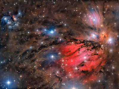 |
| Object |
NGC2170 |
| Author |
CielAustral Group |
| Camera |
C3-61000 |
| Filters |
L, R, G, B, Hα |
| Exposure |
43 hours 26
minutes |
| Telescope |
450 mm RC, reduced
to f/4 |
|
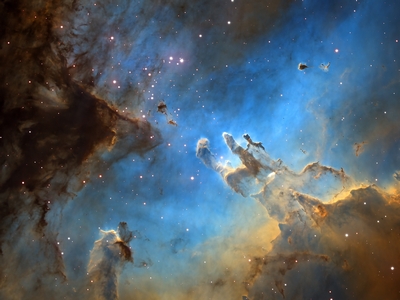 |
| Object |
M16 “Eagle” nebula |
| Author |
Wolfgang Promper |
| Camera |
C3-61000 |
| Filters |
Hα, SII, OIII |
| Exposure |
3 hours |
| Telescope |
600 mm RC, reduced
to f/4.5 |
|
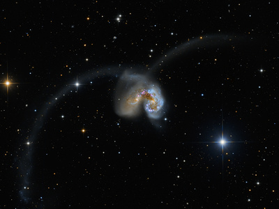 |
| Object |
NGC 4038 / NGC 4039 “Antennae”
galaxies |
| Author |
Wolfgang Promper |
| Camera |
C3-61000 |
| Filters |
Hα, SII, OIII, L, R, G,
B |
| Exposure |
5 hours |
| Telescope |
600 mm RC, reduced
to f/4.5 |
|
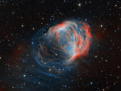 |
| Object |
SH2-274 “Medusa” nebula |
| Author |
Wolfgang Promper |
| Camera |
C3-61000 |
| Filters |
Hα, OIII, R, G, B |
| Exposure |
8.25 hours |
| Telescope |
600 mm RC, reduced
to f/4.5 |
|
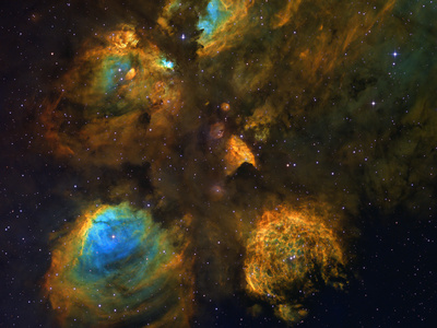 |
| Object |
NGC6334 nebula |
| Author |
Wolfgang Promper |
| Camera |
C3-61000 |
| Filters |
Hα, SII, OIII |
| Exposure |
9 hours |
| Telescope |
600 mm RC, reduced
to f/4.5 |
|
 |
| Object |
NGC1977 “Running man” nebula |
| Author |
Wolfgang Promper |
| Camera |
C3-61000 |
| Filters |
L, R, G, B |
| Exposure |
5.5 hours |
| Telescope |
600 mm RC, reduced
to f/4.5 |
|
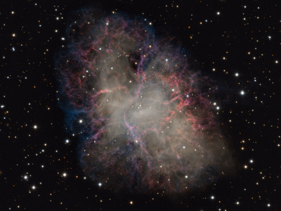 |
| Object |
M1 “Crab” nebula |
| Author |
Wolfgang Promper |
| Camera |
C3-61000 |
| Filters |
L, R, G, B |
| Exposure |
8 hours |
| Telescope |
600 mm RC, reduced
to f/4.5 |
|
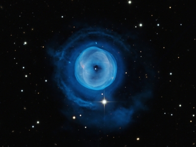 |
| Object |
IV5148 nebula |
| Author |
Wolfgang Promper |
| Camera |
C3-61000 |
| Filters |
Hα, OIII, R, G, B |
| Exposure |
9 hours |
| Telescope |
600 mm RC, reduced
to f/4.5 |
|
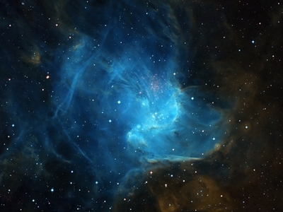 |
| Object |
IC346 nebula |
| Author |
Wolfgang Promper |
| Camera |
C3-61000 |
| Filters |
Hα, SII, OIII |
| Exposure |
12 hours |
| Telescope |
600 mm RC, reduced
to f/4.5 |
|
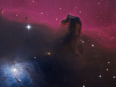 |
| Object |
“Horse Head” nebula |
| Author |
Wolfgang Promper |
| Camera |
C3-61000 |
| Filters |
L, R, G, B |
| Exposure |
2.5 hours |
| Telescope |
600 mm RC, reduced
to f/4.5 |
|
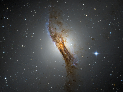 |
| Object |
NGC5128 “Centaurus A” galaxy |
| Author |
Wolfgang Promper |
| Camera |
C3-61000 |
| Filters |
L, R, G, B |
| Exposure |
4.5 hours |
| Telescope |
600 mm RC, reduced
to f/4.5 |
|
 |
| Object |
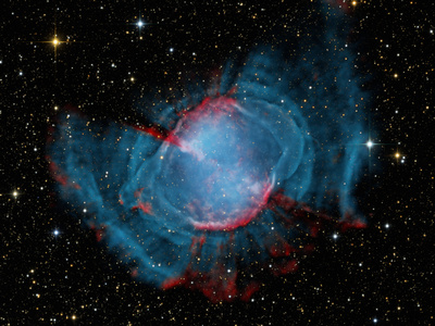
M27 “Dumbbell” nebula |
| Author |
Wolfgang Promper |
| Camera |
C3-61000 |
| Filters |
L, R, G, B, Hα,
OIII |
| Exposure |
9 hours |
| Telescope |
600 mm RC, reduced
to f/4.5 |
|
 |
| Object |
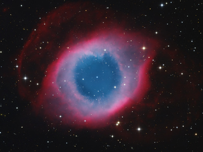
NGC7293 “Helix” nebula |
| Author |
Wolfgang Promper |
| Camera |
C3-61000 |
| Filters |
L, R, G, B, Hα, |
| Exposure |
8.7 hours |
| Telescope |
600 mm RC, reduced
to f/4.5 |
|
 |
| Object |
NGC3324 nebula |
| Author |
Wolfgang Promper |
| Camera |
C3-61000 |
| Filters |
L, R, G, B |
| Exposure |
6 hours |
| Telescope |
600 mm RC, reduced
to f/4.5 |
|
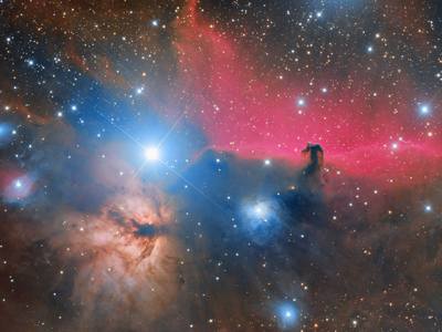 |
| Object |
“Horse head” and “Flame”
nebulae |
| Author |
Efrem Frigeni |
| Camera |
C3-26000 |
| Filters |
R, G, B |
| Exposure |
5 hours |
| Telescope |
FSQ 106/530 + CCA250/1250 |
|
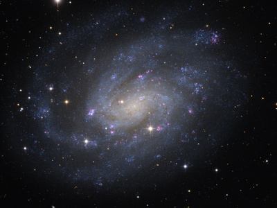 |
| Object |
NGC300 galaxy |
| Author |
Wolfgang Promper |
| Camera |
C3-61000 |
| Filters |
L, R, G, B, Hα, |
| Exposure |
7.5 hours |
| Telescope |
600 mm RC, reduced
to f/4.5 |
|
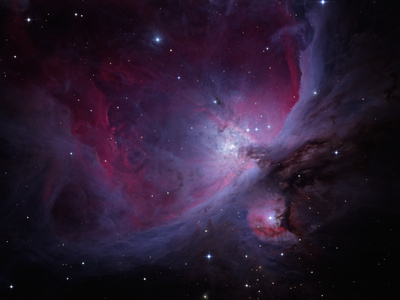 |
| Object |
M42 “Great Orion Nebula” |
| Author |
Wolfgang Promper |
| Camera |
C3-61000 |
| Filters |
R, G, B |
| Exposure |
30 minutes |
| Telescope |
600 mm RC, reduced
to f/4.5 |
|
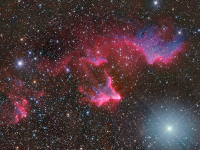 |
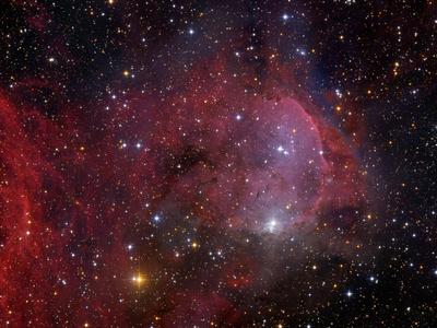
| Object |
IC59 and IC63 nebulae |
| Author |
Martin Myslivec |
| Camera |
C3-61000 |
| Filters |
Hα, R, G, B |
| Exposure |
21.5 hours |
| Telescope |
400 mm, f/4
Newtonian telescope |
|
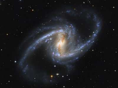 |
| Object |
NGC1365 galaxy |
| Author |
Wolfgang Promper |
| Camera |
C3-61000 |
| Filters |
L, R, G, B |
| Exposure |
4.5 hours |
| Telescope |
600 mm RC, reduced
to f/4.5 |
|
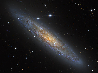 |
| Object |
NGC253 galaxy |
| Author |
Wolfgang Promper |
| Camera |
C3-61000 |
| Filters |
L, R, G, B |
| Exposure |
4 hours |
| Telescope |
600 mm RC, reduced
to f/4.5 |
|
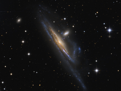 |
| Object |
NGC1532 galaxy |
| Author |
Wolfgang Promper |
| Camera |
C3-61000 |
| Filters |
L, R, G, B |
| Exposure |
4.7 hours |
| Telescope |
600 mm RC, reduced
to f/4.5 |
|
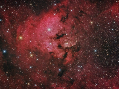 |
| Object |
SH2-171 nebula |
| Author |
Andrea Lucchetti |
| Camera |
C3-61000 |
| Filters |
R, G, B |
| Exposure |
3 hours |
| Telescope |
200 mm, f/4.5
Newtonian telescope |
|
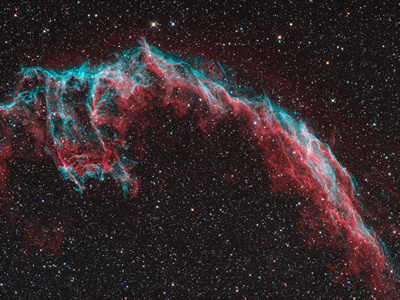 |
| Object |
NGC6992 “Veil Nebula” |
| Author |
Martin Myslivec |
| Camera |
C3-61000 |
| Filters |
Hα, OIII, R, G, B |
| Exposure |
19 hours |
| Telescope |
400 mm, f/4
Newtonian telescope |
|
| 